
Rotary
Bar Screen
Advanced rotary solid-liquid separation for municipal wastewater plants, industrial screening stations, and water intake facilities. Continuous, self-cleaning operation with minimal maintenance.
What Is A
Rotary Bar Screen?
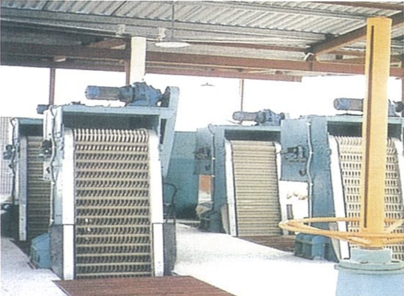
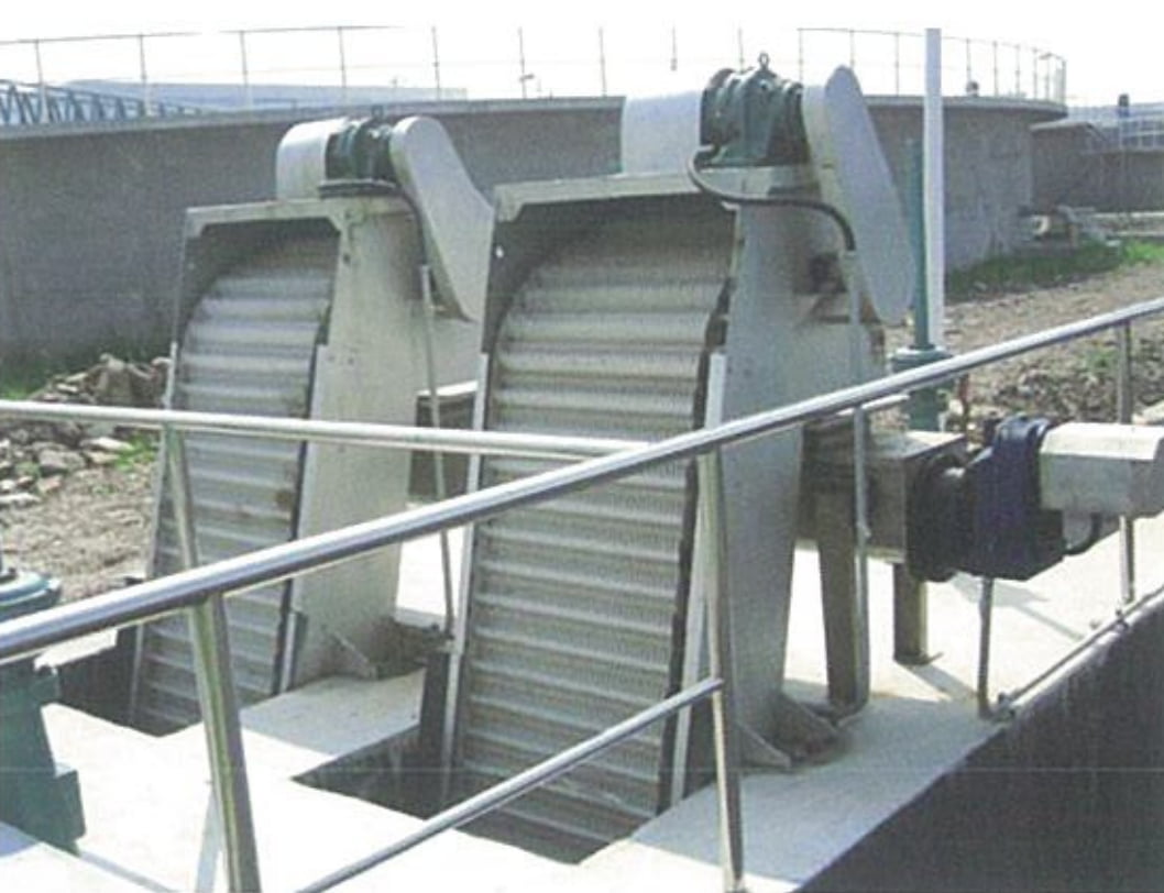
The Rotary Bar Screen (also known as a Rotary Grid Sewage Cleaner) is an advanced solid-liquid separation device used in water treatment. It provides continuous, automated removal of solids and debris from water flows.
Rake teeth assembled on a transverse shaft form a rake chain. As the drive unit moves the chain upward, debris in the water is captured while liquid passes freely through the bar gaps. At the top, the chain reverses and solids fall off by gravity — completing one continuous, uninterrupted cycle.
- Municipal sewage treatment plants
- District wastewater pre-treatment systems
- Urban stormwater pump stations
- Water supply plant intakes
- Power plant cooling water intakes
- Textile and dyeing industries
- Food processing and aquaculture
- Papermaking and slaughterhouse facilities
- Leather tanning wastewater systems
Why Choose Our
Rotary Bar Screen
Low-Noise Drive
Cycloidal pin-wheel or helical gear motor direct drive — quiet operation, compact structure, smooth and stable running.
Rigid Frame Design
Integral frame construction delivers high rigidity. Easy to install with minimal daily maintenance requirements.
Two Rake Tooth Specs
Available in t=100mm and t=200mm chain pitch to match different flow and solid load requirements.
Local / Remote Control
Operable on-site or via remote control systems. Simple, flexible operation for various plant configurations.
Dual Overload Protection
Mechanical shear pin and electrical overcurrent protection work together to keep the equipment safe during unexpected overloads.
Parallel Configuration
For channel widths ≥1500mm, parallel-unit arrangement ensures overall structural integrity and strength.
How It Works
Intake
Wastewater enters from the channel inlet. Rake chain moves upward from the bottom.
Screening
Rake teeth capture solids and debris. Liquid passes freely through bar gaps.
Discharge
At the top apex, chain reverses. Solids fall off by gravity into collection trough.
Repeat
Continuous cycle restarts automatically — uninterrupted 24/7 operation.
Technical Parameters &
Installation Dimensions
| Parameter | Model | –500 | –600 | –700 | –800 | –900 | –1000 | –1100 | –1200 | –1300 | –1400 | –1500 |
|---|---|---|---|---|---|---|---|---|---|---|---|---|
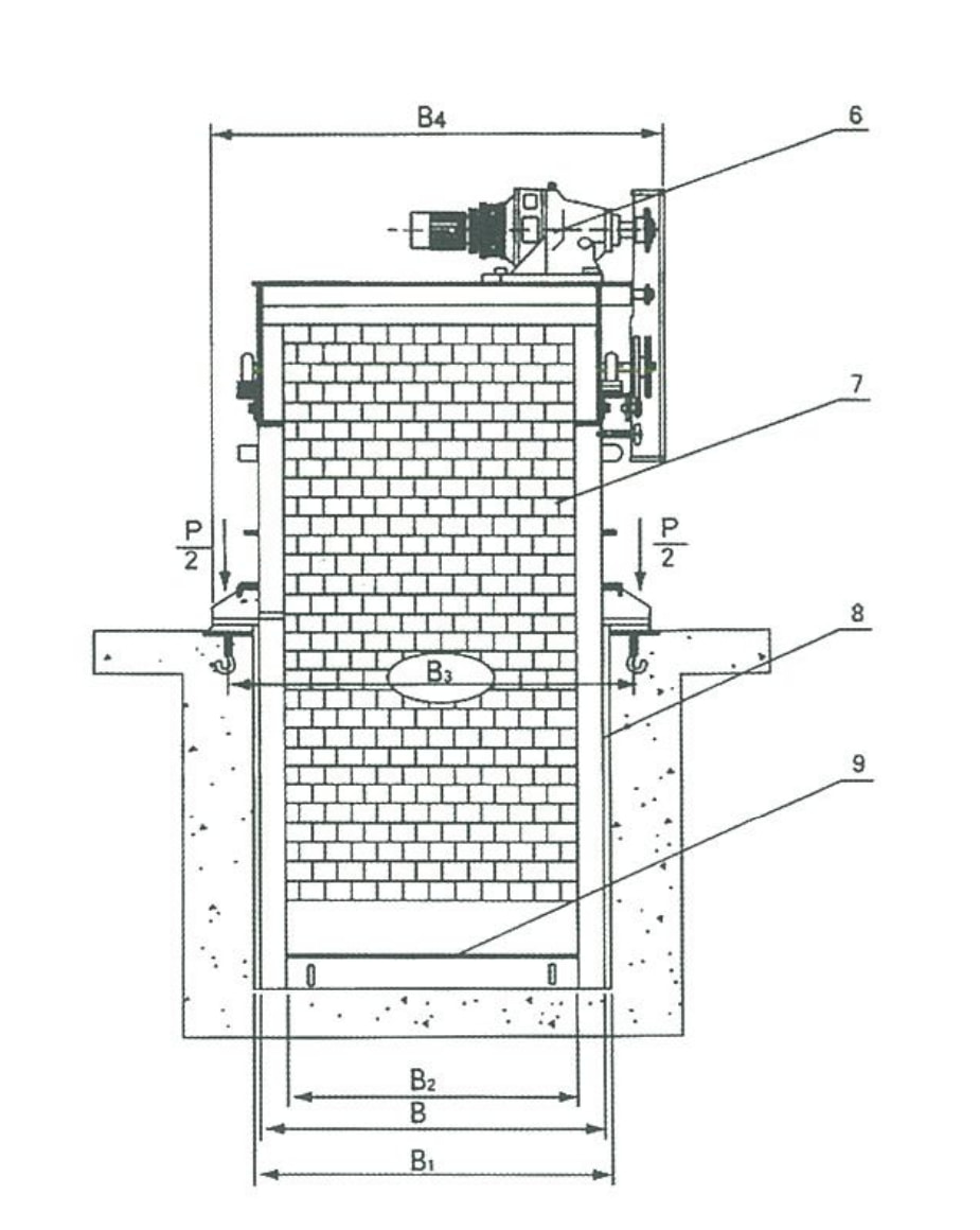
| Equipment Width B (mm) | — | 500 | 600 | 700 | 800 | 900 | 1000 | 1100 | 1200 | 1300 | 1400 | 1500 |
| Channel Width B₁ (mm) | B + 100 | |||||||||||
| Effective Grid Width B₂ (mm) | B − 157 | |||||||||||
| Foundation Bolt Spacing B₃ (mm) | B + 200 | |||||||||||
| Total Equipment Width B₄ (mm) | B + 350 | |||||||||||
| Rake Tooth Spacing b (mm) | t = 100 | 1 ≤ b ≤ 50 | ||||||||||
| t = 150 | 10 < b ≤ 50 | |||||||||||
| Installation Angle α (°) | 60 ~ 85 | |||||||||||
| Channel Depth H (mm) | 800 ~ 12,000 | |||||||||||
| Discharge Outlet Height H₁ (mm) | 600 ~ 1,200 | |||||||||||
| Total Equipment Height H₂ (mm) | H + H₁ + 1,500 | |||||||||||
| Rear Frame Height H₃ (mm) | t = 100 | ≈ 1,000 | ||||||||||
| t = 150 | ≈ 1,100 | |||||||||||
| Rake Speed V (m/min) | ≈ 2.1 | |||||||||||
| Motor Power N (kW) | 0.55 ~ 1.1 | 0.75 ~ 1.5 | 1.1 ~ 2.2 | 1.5 ~ 3.0 | ||||||||
| Head Loss (mm) | ≤ 20 (clean condition) | |||||||||||
| Civil Load | P₁ (kN) | 20 | 25 | |||||||||
| P₂ (kN) | 8 | 10 | ||||||||||
| ΔP (kN) | 1.5 | 2.0 | ||||||||||
| Note: P is calculated at H = 5.0 m. For each additional 1 m in H, total load P = P₁ (or P₂) + ΔP. t = chain pitch of rake teeth. | ||||||||||||
Flow Rate Table
| Parameter | Model | –500 | –600 | –700 | –800 | –900 | –1000 | –1100 | –1200 | –1300 | –1400 | –1500 |
|---|---|---|---|---|---|---|---|---|---|---|---|---|
| Upstream Water Depth H₃ (m) | 1.0 | |||||||||||
| Approach Velocity V’ (m/s) | 0.8 | |||||||||||
| Bar Spacing b (mm) | 1 | 0.03 | 0.04 | 0.05 | 0.06 | 0.07 | 0.08 | 0.08 | 0.09 | 0.10 | 0.11 | 0.12 |
| 3 | 0.07 | 0.09 | 0.10 | 0.12 | 0.14 | 0.16 | 0.18 | 0.20 | 0.22 | 0.24 | 0.26 | |
| 5 | 0.09 | 0.11 | 0.14 | 0.16 | 0.18 | 0.21 | 0.23 | 0.26 | 0.28 | 0.31 | 0.33 | |
| 10 | 0.11 | 0.14 | 0.17 | 0.21 | 0.24 | 0.27 | 0.30 | 0.33 | 0.37 | 0.40 | 0.43 | |
| 15 | 0.13 | 0.16 | 0.20 | 0.24 | 0.27 | 0.31 | 0.34 | 0.38 | 0.42 | 0.45 | 0.49 | |
| 20 | 0.14 | 0.17 | 0.21 | 0.25 | 0.29 | 0.33 | 0.37 | 0.41 | 0.45 | 0.49 | 0.53 | |
| 25 | 0.14 | 0.18 | 0.22 | 0.27 | 0.31 | 0.35 | 0.39 | 0.43 | 0.47 | 0.51 | 0.55 | |
| 30 | 0.15 | 0.19 | 0.23 | 0.27 | 0.32 | 0.36 | 0.40 | 0.45 | 0.49 | 0.53 | 0.57 | |
| 40 | 0.15 | 0.20 | 0.24 | 0.29 | 0.33 | 0.38 | 0.42 | 0.46 | 0.51 | 0.55 | 0.60 | |
| 50 | 0.16 | 0.20 | 0.25 | 0.29 | 0.34 | 0.39 | 0.43 | 0.48 | 0.52 | 0.57 | 0.61 | |
| Flow rate Q (m³/m) — flow per unit width of screen. Conditions: H₃ = 1.0 m, V’ = 0.8 m/s. | ||||||||||||
Installation Dimensions
& Components
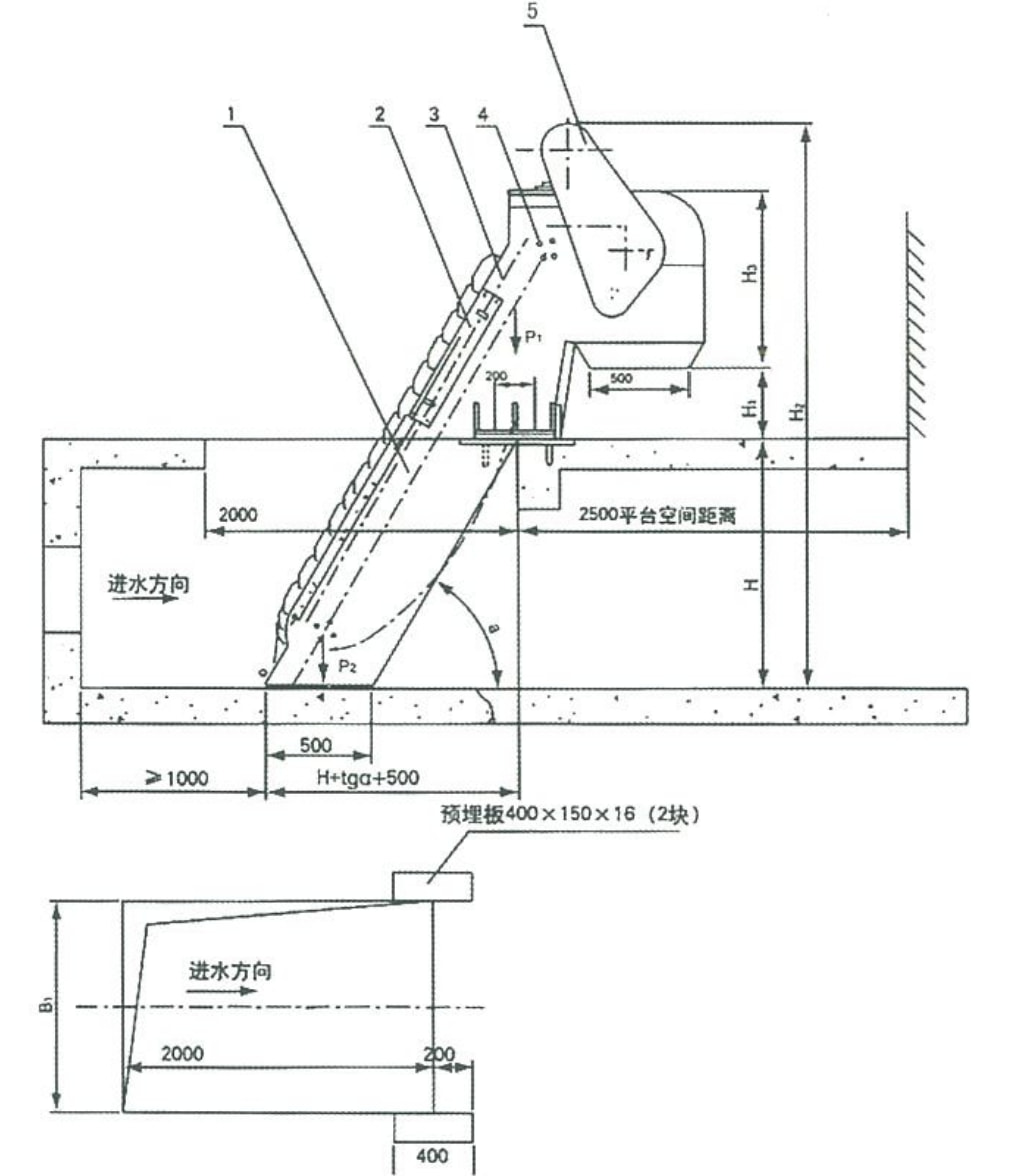
Key Installation Notes
- Minimum upstream channel length: 2,000mm
- Platform clearance space: 2,500mm
- Installation angle range: 60°–85°
- Two pre-embedded steel plates required (400×150×16mm)
- Water flow direction must align with equipment intake
Request A Quote
Or Technical Consultation
Tell us your channel dimensions, flow rate, and screening requirements — we’ll recommend the right model and provide a detailed proposal.