
Chain Link
Rotary Bar Screen
Cleaner
Heavy-duty chain-driven bar screen for continuous automated removal of coarse solids from municipal and industrial wastewater channels. Handles wide channels up to 3,000 mm with reliable, low-maintenance operation.
What Is A Chain Link
Rotary Bar Screen Cleaner?
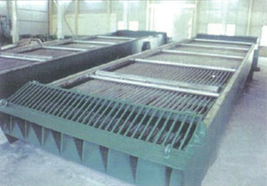
The Chain Link Rotary Bar Screen Cleaner is a heavy-duty coarse screening device designed for high-flow wastewater channels. It is particularly suited to municipal sewage pump stations, stormwater intake facilities, and industrial pre-treatment systems where large solids must be intercepted continuously.
Fixed bar panels form the screening face. Rake tooth plates mounted on a continuous chain assembly mesh into the bar gaps. As the drive unit rotates the chain upward, captured debris is lifted to the discharge outlet at the platform level, where it falls by gravity into a collection bin or conveyor — completing one uninterrupted cycle.
The spacing between adjacent rake tooth plates is 2.0–2.5 m, with an intermediate support baffle to handle larger debris loads. This design suits wide channels (800–3,000 mm) and deep installations (up to 12,000 mm) that exceed the capacity of standard rotary bar screens.
- Municipal sewage pump stations and headworks
- Urban stormwater and combined sewer pump stations
- Water supply plant intakes
- River and reservoir intake screening
- Industrial wastewater pre-treatment
- Food processing and aquaculture facilities
- Papermaking and textile industries
- Power plant cooling water intakes
- Slaughterhouse and tannery wastewater
Why Choose Our
Chain Link Rotary Bar Screen
Low-Noise Drive
Cycloidal pin-wheel or helical gear reducer drives the chain via transmission linkage — quiet, compact, and smooth under continuous load.
Precision Rake Plates
CNC-machined rake tooth plates with high dimensional accuracy. Spacing of 2.0–2.5 m between plate sets, with an intermediate support baffle for effective large-debris capture.
Rigid Integral Frame
One-piece welded frame structure delivers high rigidity and stability. Easy installation with minimal daily maintenance requirements.
Local / Remote Control
Operable on-site or via remote control systems. Compatible with timed, level-differential, or manual actuation modes.
Dual Overload Protection
Mechanical shear pin in the drive sprocket and electrical overcurrent relay in the control cabinet provide independent safeguards against overload.
Wide Channel Coverage
Handles channel widths from 800 mm to 3,000 mm and depths up to 12,000 mm — well beyond the range of standard rotary bar screens.
How It Works
Intake
Wastewater flows through the fixed bar panel. Solids larger than the bar spacing are retained on the screen face.
Raking
Drive unit rotates the traction chain. Rake tooth plates mesh into bar gaps and lift captured debris upward.
Discharge
At the top, debris falls by gravity from the rake plates into a collection trough or conveyor at platform level.
Repeat
Chain returns submerged for the next cycle — continuous, uninterrupted 24/7 screening operation.
Technical Parameters &
Installation Dimensions
| Parameter | Model | –800 | –1000 | –1200 | –1400 | –1600 | –1800 | –2000 | –2200 | –2400 | –2600 | –2800 | –3000 |
|---|---|---|---|---|---|---|---|---|---|---|---|---|---|
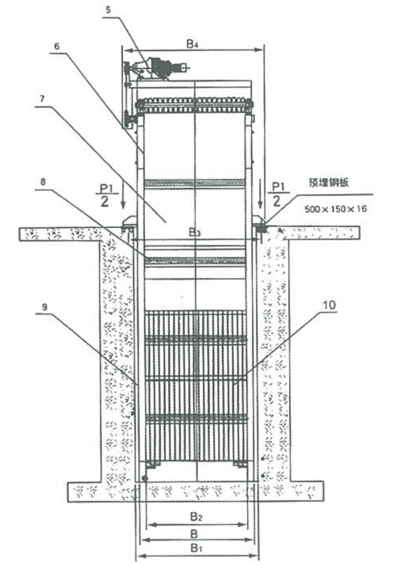
| Equipment Width B (mm) | — | 800 | 1000 | 1200 | 1400 | 1600 | 1800 | 2000 | 2200 | 2400 | 2600 | 2800 | 3000 |
| Channel Width B₁ (mm) | B + 100 | ||||||||||||
| Effective Grid Width B₂ (mm) | B − 166 | ||||||||||||
| Foundation Bolt Spacing B₃ (mm) | B + 200 | ||||||||||||
| Total Equipment Width B₄ (mm) | B + 350 | ||||||||||||
| Bar Spacing b (mm) | 20 ~ 100 | ||||||||||||
| Installation Angle α (°) | 60 ~ 80 | ||||||||||||
| Channel Depth H (mm) | 2,000 ~ 12,000 (per client requirement) | ||||||||||||
| Discharge Outlet Height H₁ (mm) | 600 ~ 1,200 (per client requirement) | ||||||||||||
| Total Equipment Height H₂ (mm) | H + H₁ + 1,500 | H + H₁ + 1,600 | |||||||||||
| Bar Length L (mm) | (Max. water depth + 600) / sinα (per client requirement) | ||||||||||||
| Traction Chain Speed V (m/min) | ≤ 3.0 | ||||||||||||
| Motor Power N (kW) | 0.75 ~ 1.5 | 1.1 ~ 2.2 | 1.5 ~ 3.0 | ||||||||||
| Civil Load | P₁ (kN) | 18.0 | 22.5 | 30.0 | |||||||||
| P₂ (kN) | 8.0 | 12.5 | 20.0 | ||||||||||
| ΔP (kN) | 1.0 | 1.5 | 2.0 | ||||||||||
| Note: P is calculated at H = 5.0 m. For each additional 1 m in H, total load P = P₁ (or P₂) + ΔP. | |||||||||||||
Flow Rate Table
| Parameter | Model | –800 | –1000 | –1200 | –1400 | –1600 | –1800 | –2000 | –2200 | –2400 | –2600 | –2800 | –3000 |
|---|---|---|---|---|---|---|---|---|---|---|---|---|---|
| Upstream Water Depth H₃ (m) | 2.0 | ||||||||||||
| Approach Velocity V’ (m/s) | 0.8 | ||||||||||||
| Bar Spacing b (mm) |
20 | 0.57 | 0.76 | 0.94 | 1.12 | 1.30 | 1.48 | 1.66 | 1.84 | 2.03 | 2.21 | 2.39 | 2.57 |
| 30 | 0.65 | 0.85 | 1.05 | 1.26 | 1.46 | 1.67 | 1.87 | 2.07 | 2.28 | 2.48 | 2.69 | 2.89 | |
| 40 | 0.69 | 0.91 | 1.12 | 1.34 | 1.56 | 1.78 | 2.00 | 2.21 | 2.43 | 2.65 | 2.87 | 3.08 | |
| 50 | 0.72 | 0.95 | 1.17 | 1.40 | 1.63 | 1.85 | 2.08 | 2.30 | 2.53 | 2.76 | 2.99 | 3.21 | |
| 60 | 0.74 | 0.97 | 1.21 | 1.44 | 1.67 | 1.90 | 2.14 | 2.37 | 2.60 | 2.84 | 3.07 | 3.30 | |
| 70 | 0.75 | 0.99 | 1.23 | 1.47 | 1.71 | 1.94 | 2.18 | 2.42 | 2.66 | 2.90 | 3.13 | 3.37 | |
| 80 | 0.77 | 1.01 | 1.25 | 1.49 | 1.73 | 1.98 | 2.22 | 2.46 | 2.70 | 2.94 | 3.18 | 3.43 | |
| 90 | 0.78 | 1.02 | 1.27 | 1.51 | 1.76 | 2.00 | 2.24 | 2.49 | 2.73 | 2.97 | 3.22 | 3.47 | |
| 100 | 0.78 | 1.03 | 1.28 | 1.53 | 1.77 | 2.02 | 2.27 | 2.51 | 2.76 | 3.01 | 3.26 | 3.50 | |
| Flow rate Q (m³/m) — flow per unit width of screen. Conditions: H₃ = 2.0 m, V’ = 0.8 m/s. | |||||||||||||
Installation Dimensions
& Components
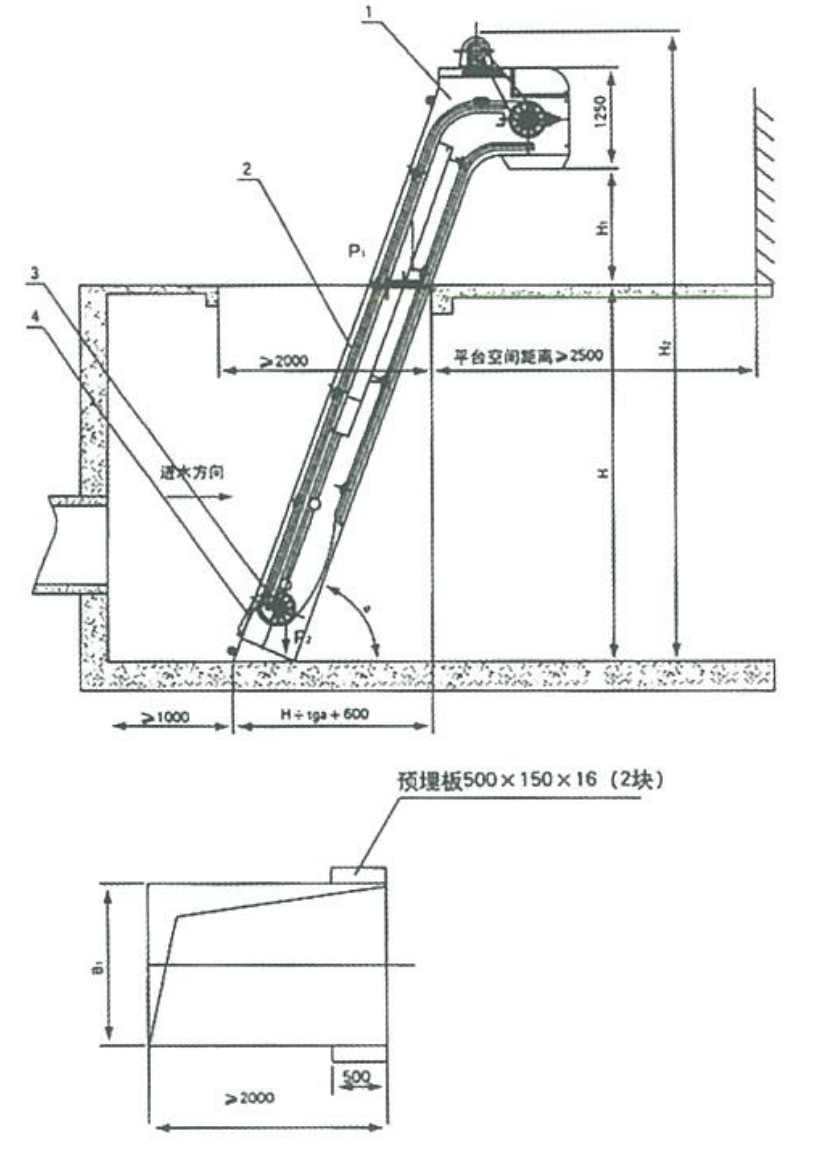
Key Installation Notes
- Minimum upstream channel length: 1,000 mm
- Platform clearance space: ≥ 2,500 mm
- Installation angle range: 60°–80°
- Two pre-embedded steel plates required: 500×150×16 mm
- Bar length L = (max. water depth + 600) / sinα
- Water flow direction must align with equipment intake
Request A Quote
Or Technical Consultation
Tell us your channel dimensions, flow rate, and bar spacing requirements — we’ll recommend the right model and provide a detailed proposal.