
Fiber Disc
Microfilter
A gravity-driven, cloth media disc filter delivering tertiary-level filtration of 10–100 μm for municipal and industrial wastewater. Up to 20 filter discs per unit, maximum flow 1,500 m³/h. Continuous operation with automatic backwash — no pump required for the filtration cycle.
What Is A Fiber Disc
Microfilter?
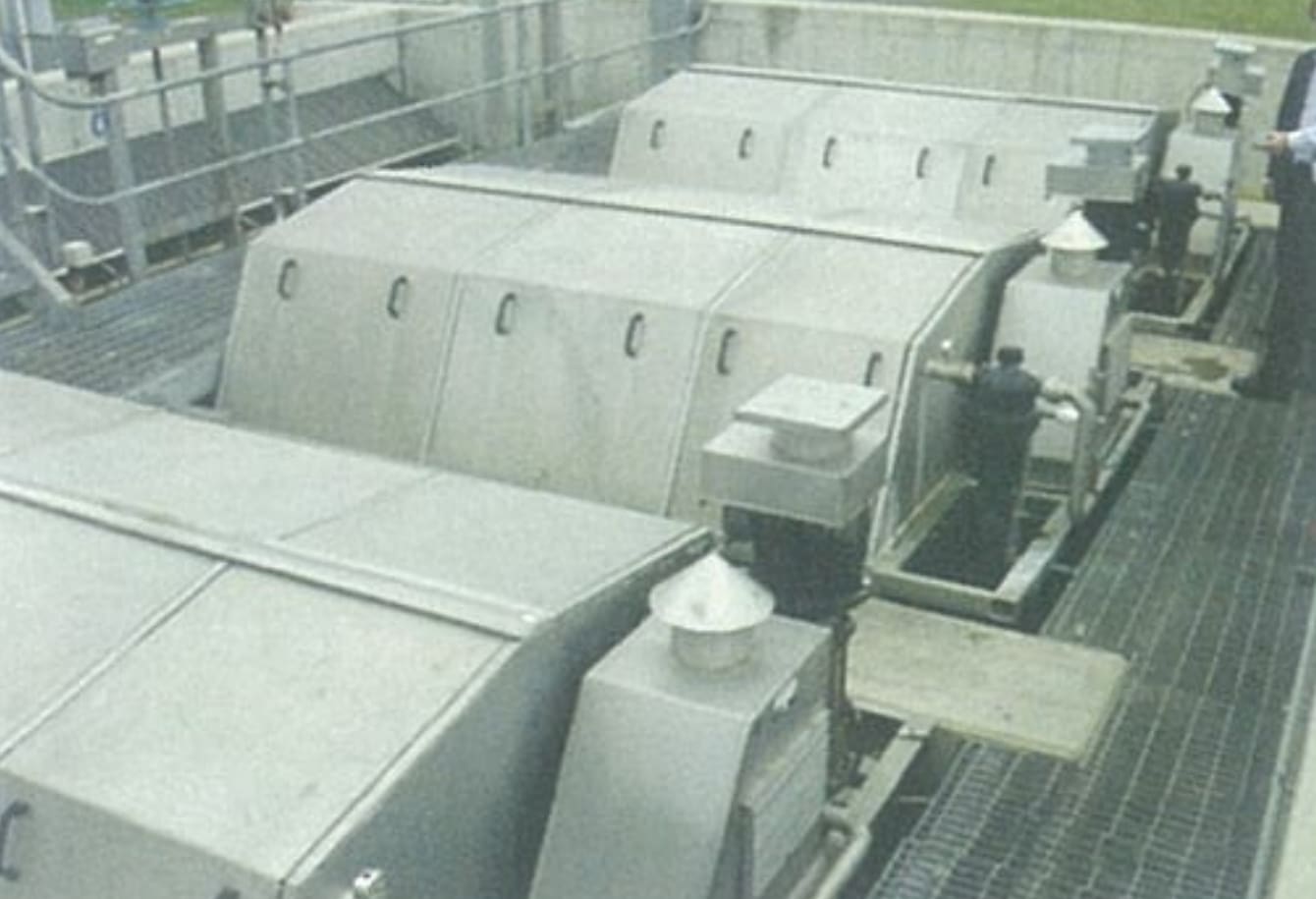
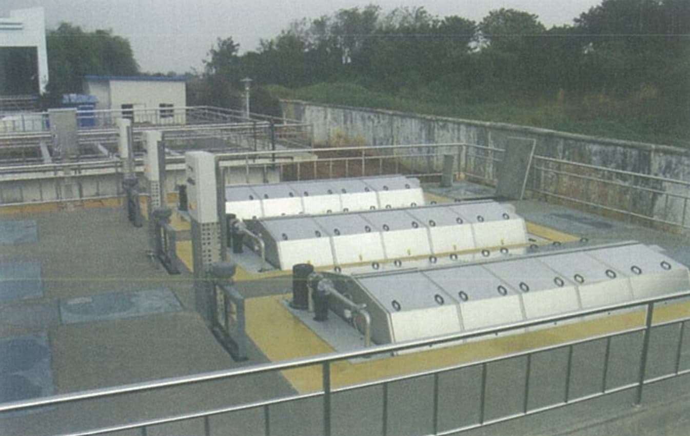
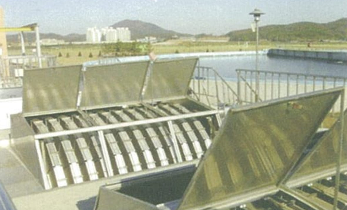
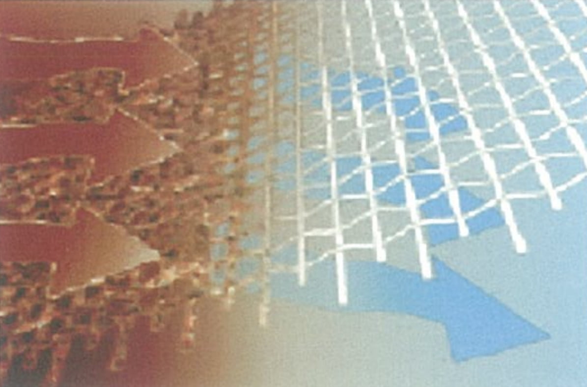
The Fiber Disc Microfilter is a gravity-driven cloth media disc filter designed for the tertiary treatment of large volumes of municipal and industrial wastewater. The machine consists of a series of horizontally oriented, rotatable filter discs mounted on a central shaft drum. Each disc comprises individual stainless steel panels wrapped with a precisely defined mesh cloth.
Wastewater flows from the outside of the disc panels inward through the cloth media. Suspended solids larger than the filter opening are retained on the outer surface; filtered effluent exits from the end of the central drum. During the filtration phase, the discs remain stationary — gravity alone drives the flow, with no pumping energy required.
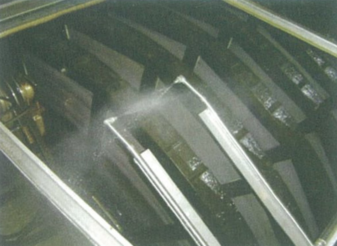
As solids accumulate on the cloth surface, differential water level rises. When the preset maximum differential is reached, the discs begin to rotate slowly and an automatic backwash system activates. Filtered water is pumped to spray nozzles that dislodge the retained solids from the outer cloth surface. A slurry collection hopper beneath each disc captures the backwash reject and routes it to the sludge discharge line. Filtration continues uninterrupted throughout the backwash cycle.
The Fiber Disc Microfilter has a single mechanical platform. Treatment capacity is determined by two variables:
- Municipal WWTP effluent tertiary polishing
- Grade 1-B to Grade 1-A effluent standard upgrade
- Pre-filtration before UV disinfection or MBR systems
- Cooling water and reclaimed water preparation
- Industrial process water and reuse water production
- Surface water pre-treatment before potable supply
- Pre-treatment before discharge to rivers or sea outfalls
- Pulp & paper, food processing, synthetic materials industries
Why Choose Our
Fiber Disc Microfilter
Gravity-Driven Filtration
No pump required during the filtration phase. Gravity head difference drives flow through the cloth media — minimal energy consumption compared to pressure-driven systems.
Precisely Defined Filter Opening
Mesh cloth media with clearly defined aperture (10–100 μm) provides reliable, consistent filtration performance — unlike granular media where particle size distribution varies.
Continuous Operation
Filtration continues uninterrupted during backwash cycles. Disc rotation and backwash spray clean the cloth while flow continues — no downtime and no need for a standby unit.
Very Low Head Loss
Gravity filtration principle means minimal hydraulic head loss across the filter. Suitable for retrofitting into existing treatment trains without civil engineering modifications.
Compact & Modular
Fully enclosed structure with small footprint — up to 75% smaller than equivalent sand filtration. Modular disc configuration allows capacity to be added without replacing the unit.
Reduces TSS, COD, BOD & TP
Achieves TSS effluent concentrations as low as 5 mg/L. Simultaneously reduces filterable COD, BOD, and total phosphorus — delivering measurable improvement in discharge quality.
Installs in Concrete or Steel Tank
Can be optimally installed in owner-supplied concrete basins or our standard stainless steel enclosures — flexible for new builds and upgrade projects alike.
High Submersion Ratio
Up to 60% of the disc area is submerged at any time, maximizing the active filtration surface available per unit footprint.
Safe Effluent Quality Control
Automated differential level control triggers backwash precisely when needed. Effluent quality remains consistent and within specification regardless of influent solids load variation.
How It Works
Static Filtration
Wastewater flows outside-in through the stationary cloth disc panels. Solids deposit on the outer surface; filtered effluent exits via the central drum.
Level Detection
As solids accumulate on the cloth, differential water level rises. Level sensors detect when the preset maximum differential is reached.
Backwash Rotation
Discs begin to rotate slowly. Backwash pump supplies filtered water to spray nozzles that dislodge retained solids from the cloth outer surface.
Reject Discharge
Backwash slurry is captured by under-disc collection hoppers and routed to the sludge discharge line. Disc returns to static mode when water level drops to setpoint.
Technical Specifications
| Parameter | Value / Range |
|---|---|
| Filter Media | Stainless steel mesh cloth (standard SS304; SS316L optional) |
| Filter Opening (aperture) | 10 – 100 μm (configured per project requirement) |
| Max. Discs per Unit | 20 |
| Max. Flow per Unit | 1,500 m³/h (20 discs, pre-biological treatment) |
| Max. Submersion Ratio | 60% of disc area |
| Filtration Mode | Outside-in, gravity-driven — no pump during filtration phase |
| Backwash Trigger | Differential water level sensor (automatic) |
| Backwash Water Source | External supply (filtered effluent or clean water); external pump required |
| Operation During Backwash | Continuous — filtration not interrupted during cleaning cycle |
| Enclosure Material | SS304 stainless steel (standard); installation in concrete basin also available |
| Effluent TSS (typical) | ≤ 5 mg/L (depending on application and aperture selection) |
| Head Loss | Very low — gravity principle only |
| Footprint vs. Sand Filter | Up to 75% reduction in required floor area |
| Note: The Fiber Disc Microfilter has a single mechanical platform. Capacity is scaled by adjusting the number of filter discs (1–20) and selecting the appropriate filter aperture (10–100 μm) for the target application. | |
Where It Is Used
Pre-Discharge Filtration
Reducing COD, BOD, and total phosphorus in effluent before discharge to receiving water bodies — rivers, lakes, and coastal outfalls. Particularly effective in projects with only mechanical primary treatment, where micro-filtration replaces conventional secondary processes.
Pre-Advanced Treatment
Removing fine suspended particles before UV disinfection or membrane filtration (MBR, hollow fiber, RO). Separation of fine solids, hair, and fiber particles prevents fouling of membranes and ensures effective UV transmittance — critical for MBR protection.
Resource Recovery & Reuse
Producing reclaimed water for cooling systems, industrial process water, and irrigation reuse. Recovers valuable suspended matter — filtered water can be reused on-site; captured nutrient-rich solids are available for agricultural application.
Industrial Process Water
Pre-treatment of industrial effluent before discharge to municipal sewer — regulatory compliance at source. Applications include pulp & paper, food processing, textiles, and synthetic materials industries where suspended solids must be reduced before sewer discharge.
Grade Upgrade (1-B to 1-A)
Polishing secondary-treated effluent to achieve China Grade 1-A discharge standards from Grade 1-B — a common plant upgrade requirement driven by tightening environmental regulations for municipal wastewater treatment plants.
Surface Water Pre-Treatment
Pre-filtration of surface water from rivers, lakes, or reservoirs before conventional potable water treatment or pre-UV disinfection. Reduces suspended solids load on downstream processes, lowering coagulant and disinfectant demand.
Installation & Components
Key Installation Notes
- Can be installed in owner-supplied concrete basin or standard stainless steel enclosure
- Influent enters through one end of the central drum via an inlet pipe
- Filtered effluent exits from the far end of the central drum
- Backwash water supply (external pump) must be connected to spray nozzle header
- Backwash reject (slurry) exits via sludge discharge flange to sludge management
- No civil trenching or special foundations required beyond a level basin floor
Request A Quote
Or Technical Consultation
Tell us your required flow rate, target effluent quality, suspended solids concentration, and downstream process requirements — we’ll configure the right number of discs and filter aperture for your application.