
Cyclonic Grit
Chamber
Grit Remover
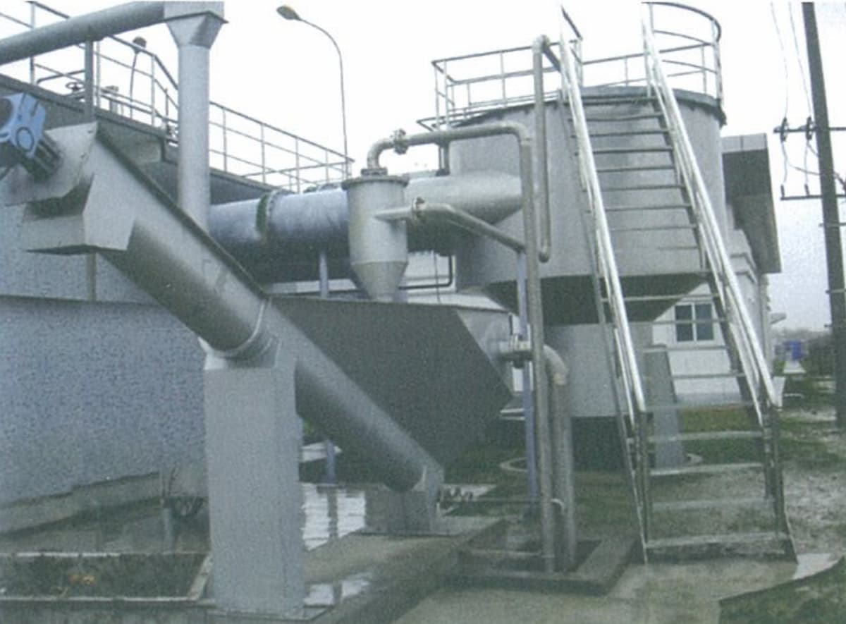
A complete grit removal system for municipal wastewater treatment plants. Hydraulic vortex action in a conical-bottom circular chamber, combined with paddle-wheel separation, air-lift extraction, and integrated spiral grit classifier — efficiently separating grit from organics before downstream biological treatment.
What Is A Cyclonic Grit
Chamber Grit Remover?
The Cyclonic Grit Chamber Grit Remover is a complete grit removal system designed for municipal wastewater treatment plant headworks. It uses a conical-bottom circular chamber fitted with an internal paddle-wheel agitator. Wastewater enters tangentially, rotating 270° (clockwise in plan view) before exiting through the effluent channel. The tangential inlet velocity drives the flow in a circular path along the chamber wall, generating a controlled vortex.
The vortex and paddle-wheel agitation create combined rotational and axial flow patterns that accelerate grit particle settling while keeping organic matter suspended. The decreasing cross-sectional area toward the chamber base progressively increases flow velocity, driving settled grit in a spiral trajectory toward the central grit hopper at the bottom. Organics rise toward the center of the chamber and are carried out with the effluent flow.
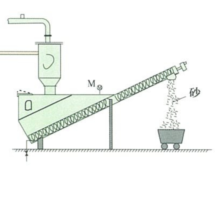
Accumulated grit in the hopper is mobilized by air agitation, lifted by air-lift pump to the grit-water separator, and then dewatered and classified by the integrated spiral grit classifier before discharge to the grit collection cart. Return water from the classifier flows back to the inlet chamber.
- Municipal wastewater treatment plant headworks
- Combined sewer overflow grit removal
- Stormwater pump station grit chambers
- Industrial wastewater pre-treatment grit removal
- Water supply plant intake grit protection
Why Choose Our
Cyclonic Grit Chamber System
Hydraulic Vortex Separation
Tangential inlet flow creates a controlled vortex without mechanical screens. Grit settles to the conical base while organics rise and exit with effluent — clean, efficient separation.
Paddle-Wheel Agitation
Internal paddle-wheel agitator creates combined rotational and axial flow components that accelerate grit settlement and prevent premature settling of organic matter.
Air-Lift Grit Extraction
Three-stage pneumatic sequence — air agitation loosens settled grit, air-flush mobilizes it, air-lift pump transfers the slurry to the separator above grade. No submerged mechanical pumps.
Integrated Spiral Classifier
Matched spiral grit classifier (screw grit washer) dewaters, classifies, and conveys clean grit in one unit. Return water flows back to the inlet channel — no separate dewatering equipment needed.
PLC Automatic Control
PLC-based control system with centralized control cabinet, master console, and drive units. Operates automatically on preset program or manually via control buttons — 6–12 extraction cycles per day.
Wide Capacity Range
Eleven models covering 34–2,315 L/s — suitable for small community plants through large municipal facilities. Matched spiral classifier models scaled to each chamber size.
How It Works
Vortex & Settle
Wastewater enters tangentially. Vortex + paddle-wheel agitation accelerates grit settling to the conical base hopper. Organics rise and exit with effluent.
Air Agitation
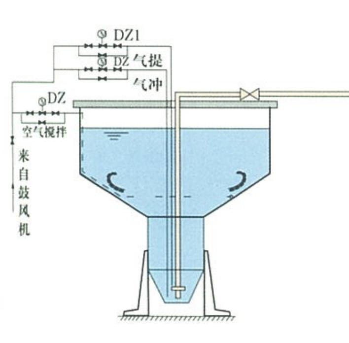
Air-flush solenoid (DZ2) opens to loosen compacted grit in the hopper. Duration: 1–2 min. Air-stir solenoid (DZ3) closes during this phase.
Air-Lift Transfer
Air-lift solenoid (DZ1) opens to pump grit-water slurry from the hopper up to the spiral grit classifier above grade. Spiral classifier starts after 15-second delay.
Classify & Discharge
Spiral classifier dewaters and conveys clean grit to collection cart. Return water recycles to inlet. Cycle: 10–30 min. System repeats 6–12 times per day.
Technical Parameters
| Grit Chamber | Air Supply | Air Flush & Air Lift Load | Blower Supply | Matched Spiral Grit Classifier | ||||||
|---|---|---|---|---|---|---|---|---|---|---|
| Model | Flow (L/s) | Air (m³/min) | Air Vol. (m³/min) | Pressure (kPa) | Air Vol. (m³/min) | Pressure (kPa) | Model | Flow (L/s) | Power (kW) | Speed (RPM) |
| 30 | 34 | 0.36 | 2.0 | 30 | 2.0 | 35 | 200 | 1–3 | 0.37 | 6.2 |
| 60 | 57 | 0.72 | 2.0 | 30 | 2.0 | 35 | 200 | 1–3 | 0.37 | 6.2 |
| 100 | 116 | 1.2 | 2.0 | 30 | 2.0 | 35 | 300 | 5–15 | 0.55 | 6.2 |
| 200 | 230 | 2.4 | 2.5 | 30 | 2.5 | 35 | 300 | 5–15 | 0.55 | 6.2 |
| 500 | 460 | 3 | 2.5 | 50 | 2.5 | 50 | 300 | 5–15 | 0.55 | 6.2 |
| 700 | 694 | 4 | 3.0 | 50 | 5.0 | 50 | 300 | 5–15 | 0.55 | 6.2 |
| 900 | 926 | 5 | 3.0 | 50 | 5.0 | 50 | 300 | 5–15 | 0.55 | 6.2 |
| 1100 | 1,157 | 6 | 3.0 | 50 | 5.0 | 50 | 300 | 5–15 | 0.55 | 6.2 |
| 1400 | 1,388 | 7 | 3.2 | 60 | 6.0 | 60 | 400 | 15–30 | 0.75 | 6.2 |
| 1600 | 1,620 | 8 | 3.2 | 60 | 8 | 60 | 400 | 15–30 | 0.75 | 6.2 |
| 2300 | 2,315 | 10 | 3.2 | 60 | 10 | 60 | 400 | 15–30 | 0.75 | 6.2 |
| Note: Air-stir solenoid DZ3 is normally open (continuous air agitation). Extraction cycle: 90–210 min (adjustable). Air flush duration: 1–2 min. Air-lift transfer duration: 10–30 min. Typical daily extraction cycles: 6–12. | ||||||||||
Installation Diagrams
& Components
Key Installation Notes
- Wastewater enters tangentially (clockwise in plan view) at the chamber inlet
- 270° rotation path before effluent exits through the outlet channel
- Air supply from blower: two separate lines (DZ1 air-lift, DZ2 air-flush, DZ3 air-stir)
- Spiral classifier installed above grade adjacent to chamber; return water line to inlet channel
- PLC control cabinet to be located in adjacent control room; DN40 air piping to chamber
- Grit collection cart positioned below classifier discharge outlet
Request A Quote
Or Technical Consultation
Tell us your design flow rate, grit characteristics, and site conditions — we’ll select the right model and matched spiral classifier and provide a full system proposal.