
Multi
Media
Filter
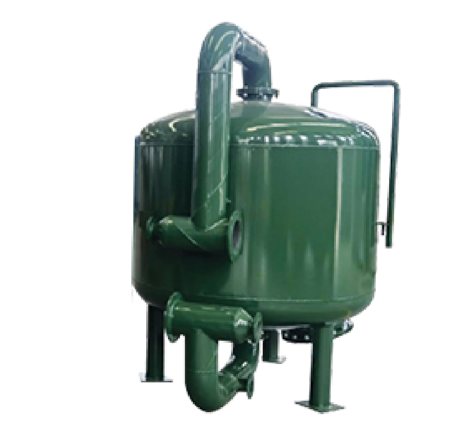
A pressure filter vessel employing three or more graded filtration media layers to deliver true depth filtration — removing suspended solids, turbidity, and fine particulates down to 5–25 micron from process water, wastewater, and industrial influent streams.
Depth Filtration
Across Multiple Media
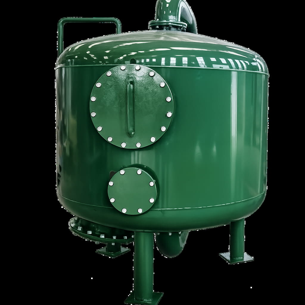
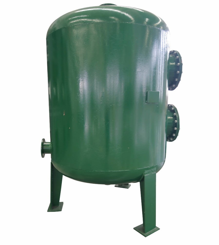
The Multi Media Filter (MMF) is a pressure filter vessel that employs three or more filtration media of differing particle size and density, arranged in a reverse-graded bed. Water flows downward through progressively finer layers, removing suspended solids at each stage rather than only at the surface — a principle known as true depth filtration. This fundamentally extends service run times and filter capacity compared to conventional single-media sand filtration.
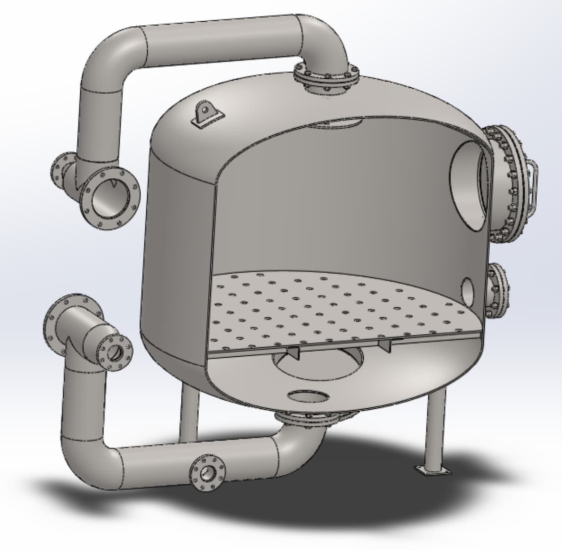
As water passes through the bed, each successive layer captures smaller particles until the treated effluent exits through the under-drain collection system. When the accumulated solids raise the differential pressure to the backwash trigger point, flow is reversed and the expanded bed releases trapped material, restoring filtration capacity. Graded support layers over the under-drain prevent media migration between cycles and ensure even flow distribution during both service and backwash.
Standard shell construction is carbon steel (Q235B) with internal epoxy coating. Stainless steel and FRP vessel options are available for corrosive service or specific process requirements.
- Pre-treatment of industrial wastewater prior to discharge
- Process and potable water production from surface or bore water
- Pre-treatment upstream of reverse osmosis (RO) membranes
- Pre-treatment upstream of demineralisation and ion exchange systems
- Food, beverage, dairy, and pharmaceutical process water polishing
- Cooling tower make-up water and recirculating water treatment
- Mining and mineral processing water clarification
- Swimming pool and aquatic facility filtration
Three-Layer
Media Bed
The graded media bed is the defining feature of MMF performance. Each layer is selected for its particle size and density so that — even after high-rate backwashing — the layers naturally re-stratify in their correct positions without manual intervention.
Why Choose This Filter
True Depth Filtration
Unlike surface-loading sand filters where solids accumulate only at the top, MMF captures particles throughout the entire depth of the media bed. This dramatically increases solids holding capacity and extends service runs between backwash cycles.
5–25 Micron Removal
The three-layer graded media configuration reliably filters particles to 10–25 µm under standard conditions, and can achieve as fine as 5 µm depending on vessel sizing, media depth, and flow rate arrangement — significantly outperforming single-media sand filtration (25–50 µm).
Self-Cleaning Backwash Cycle
Backwash is initiated automatically by differential pressure or timer. Reversed upflow expands the media bed and lifts trapped solids to the drain without manual intervention. Graded support layers prevent media migration; the bed re-stratifies naturally by density upon return to service.
Robust Pressure Vessel
Carbon steel vessel (Q235B) with internal epoxy lining, designed for continuous pressure service. Flanged manways provide full internal access for media inspection and replacement. All nozzles, connections, and flanges are standard DN ratings for straightforward site integration.
Broad Media Compatibility
Standard anthracite / silica sand / garnet combination suits the majority of municipal and industrial applications. For specific chemistries, greensand media can be substituted for iron and manganese removal, or activated carbon layers added for organic polishing and colour removal.
Low Maintenance, Long Service Life
No moving parts within the vessel. Media typically requires replacement only every 5–10 years under normal operating conditions. Straightforward backwash procedure can be manual or fully automated, minimising operator involvement and maintenance costs over the equipment lifetime.
Service & Backwash Cycle
Pressurised Inflow
Water enters the top of the vessel and is evenly distributed over the media surface by an inlet distributor, ensuring uniform loading across the full vessel diameter.
Depth Filtration
Water flows downward through anthracite, sand, and garnet layers in sequence. Each layer removes progressively finer particles, utilising the full bed depth for solids storage.
Filtered Outlet
Clarified water exits through the header-and-lateral under-drain system at the vessel base and passes to downstream treatment or the point of use.
Backwash & Regeneration
When differential pressure reaches 10 psi above the clean-bed baseline, backwash is initiated. Reversed upflow expands the bed, releases trapped solids, and restores full filtration capacity.
Model Selection Table
| Model | Vessel Diameter (mm) | Overall Height (mm) | Inlet / Outlet Connection | Backwash Connection | Flow Capacity (m³/h) | Shell Material |
|---|---|---|---|---|---|---|
| MS-GL1000 | 1000 | 2800 | DN50 | DN100 | 8 | Q235B |
| MS-GL1200 | 1200 | 2800 | DN65 | DN125 | 10 | Q235B |
| MS-GL1500 | 1500 | 2800 | DN80 | DN150 | 16 | Q235B |
| MS-GL1800 | 1800 | 2800 | DN80 | DN200 | 23 | Q235B |
| MS-GL2000 | 2000 | 2800 | DN100 | DN200 | 30 | Q235B |
| MS-GL2500 | 2500 | 2800 | DN100 | DN200 | 45 | Q235B |
| Note: Flow capacity based on standard hydraulic loading rate. Filtration to 5 µm achievable subject to media configuration and flow rate. Custom vessel diameters and stainless steel construction available on request. | ||||||
General Technical Parameters
| Parameter | Value / Range |
|---|---|
| Design Working Pressure | 0.6 MPa (standard) |
| Design Temperature | ≤ 60 °C |
| Filtration Rating | 5–25 µm (media-dependent) |
| Hydraulic Loading Rate | 8–12 m/h (service); 25–35 m/h (backwash) |
| Clean-Bed Pressure Drop | 0.02–0.05 MPa (21–50 kPa) |
| Backwash Trigger ΔP | 0.07 MPa above clean-bed baseline |
| Backwash Duration | 10–15 min (typical) |
| Media Bed Depth | Anthracite 400–600 mm / Sand 300–400 mm / Garnet 100–150 mm |
| Vessel Material | Q235B carbon steel, internal epoxy-lined (SS304 / FRP on request) |
| Inlet / Outlet Connections | Flanged (per model — see selection table) |
| Note: Parameters are indicative. Detailed engineering data is provided with technical proposal based on site-specific feed water quality and flow requirements. | |
Vessel Structure
& Key Components
Installation & Commissioning Notes
- Mount on a flat, reinforced concrete pad — verify floor load rating against vessel filled weight
- Maintain minimum 800 mm clear access on all sides for valve operation and media access
- Overhead clearance ≥ vessel height + 1,000 mm for manway access and media filling
- Inlet supply pressure should be stable 0.3–0.6 MPa — install upstream pressure regulator if required
- Backwash drain pipe to be sized to match backwash nozzle (DN100–DN200 per model)
- Commission with full flush of clean water through media before service; discard first filtered volume
- Set backwash timer and differential pressure switch before placing vessel in automatic service
Request A Quote
Or Technical Consultation
Tell us your flow rate, feed water turbidity, and downstream treatment requirements — we will recommend the right vessel size and media configuration for your application.