
Shaftless
Screw Conveyor
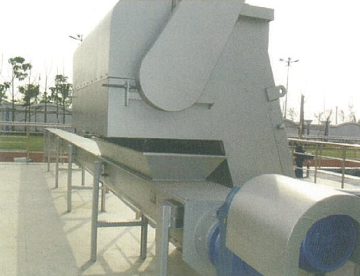
A robust, fully enclosed spiral conveyor purpose-built for transporting wastewater screenings, dewatered sludge, and grit. No center shaft means no internal bearings to foul — the only practical solution for sticky, stringy, and fibrous residuals from bar screens and dewatering equipment.
What Is A Shaftless
Screw Conveyor?
The Shaftless Screw Conveyor is a continuous U-trough conveyor designed for transporting screenings, dewatered sludge, and grit at municipal wastewater treatment plants, residential district pre-treatment facilities, stormwater and sewage pump stations, and water supply plants.
Unlike conventional shafted screw conveyors, the shaftless design eliminates the center shaft and all intermediate hanger bearings. The spiral flighting rides directly on a replaceable wear liner inside the U-trough. Material fed from the discharge port of a bar screen or dewatering machine falls onto the spiral, which moves it from one end to the other under the drive of a motorized drum. The discharge end mates with a waste collection bin or further conveying equipment for downstream handling.
The absence of a center shaft creates an open conveying bore — the key advantage when handling stringy rags, plastic bags, and fibrous screenings that would immediately wrap around and jam a conventional shafted screw conveyor.
- Screenings transport from bar screens and fine screens
- Dewatered sludge conveyance from screw presses and belt presses
- Grit transport from grit removal systems
- Municipal wastewater treatment plant headworks
- Residential and district pre-treatment facilities
- Stormwater and sewage pump stations
- Water supply plant sludge handling
- Industrial wastewater residuals transport
Transport direction is determined by the helical direction of the spiral flighting and the motor rotation direction. Bi-directional conveying is achievable by reversing motor rotation — no mechanical changes required.
Why Choose Our
Shaftless Screw Conveyor
Shaft-Mounted Helical Gearbox
Drive unit uses a shaft-mounted parallel-axis helical gear reducer — compact, stable, and smooth in operation. No separate coupling required between motor and conveyor.
Bi-Directional Conveying
Transport direction is set by spiral flighting geometry and motor rotation. Reversing the motor achieves bi-directional conveying — no mechanical reconfiguration needed.
Wear-Resistant U-Trough Liner
U-trough fitted with replaceable wear liner — high abrasion resistance, long service life, and easy replacement. Liner change does not require removing the spiral.
Non-Plugging Open Bore
No center shaft means no surface for stringy rags, plastics, or fibrous material to wrap around. Large open conveying channel — reliably non-clogging in continuous operation.
Fully Enclosed Construction
Bolt-on covers fully enclose the trough — odor containment, spill prevention, and protection of operators from contact with screenings or sludge during operation.
Low Noise, Low Maintenance
Low RPM operation reduces wear and noise. No intermediate hanger bearings to grease, align, or replace — significantly lower maintenance burden than shafted alternatives.
How It Works
Receive
Screenings or sludge fall from the bar screen or dewatering machine discharge port into the conveyor inlet.
Convey
Motorized drum drives the shaftless spiral. Material moves along the U-trough from inlet toward the discharge end.
Discharge
Material exits through the discharge outlet at the far end of the trough into a waste collection bin or next conveyor.
Continuous
Operation is continuous and fully automatic — synchronized with the upstream screen or dewatering equipment cycle.
Technical Parameters &
Installation Dimensions
| Parameter | Model | –200W | –250W | –300W | –350W | –400W |
|---|---|---|---|---|---|---|
| Nominal Spiral Diameter D (mm) | — | 200 | 250 | 300 | 350 | 400 |
| Actual Spiral Diameter Φ (mm) | — | 185 | 235 | 285 | 320 | 385 |
| Capacity Q (m³/h) | α = 0° | 1.50 | 3.60 | 6.00 | 8.40 | 11.70 |
| α = 10° | 1.35 | 3.24 | 5.40 | 7.56 | 10.53 | |
| α = 15° | 1.05 | 2.52 | 4.20 | 5.88 | 8.19 | |
| α = 20° | 0.90 | 2.16 | 3.60 | 5.04 | 7.02 | |
| Motor Power N (kW) | 0.75 ~ 5.5 (determined by conveyor length L and installation angle α) | |||||
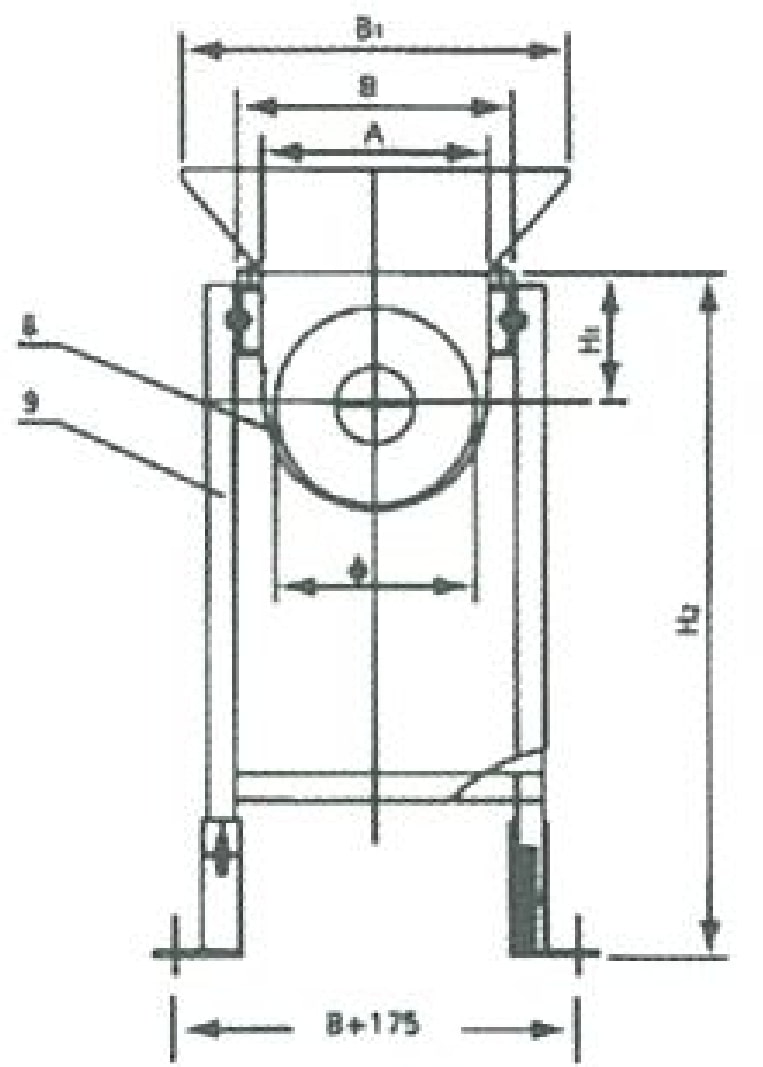
| Trough Width A (mm) | Φ + 40 | |||||
| Trough Outer Width B (mm) | Φ + 40 | |||||
| Cover Width B₁ (mm) | Φ + 110 | |||||
| Conveyor Length L (mm) | Matched to upstream equipment (per project requirement) | |||||
| Inlet Length L₁ (mm) | Per client specification | |||||
| Intermediate Section L₂ (mm) | (L − 1,000) / 2 ~ (L − 1,000) / 3 | |||||
| End Section L₃ (mm) | — | 250 | 250 | 300 | 350 | 400 |
| Trough Height H (mm) | Matched to upstream equipment | |||||
| Drive Centreline Height H₁ (mm) | — | 140 | 165 | 188 | 210 | 240 |
| Trough Depth H₂ (mm) | H − 150 | |||||
| Support Height H₃ (mm) | Matched to upstream equipment | |||||
| Note: Capacity Q is for horizontal conveying at nominal conditions. Inclined conveying reduces capacity per the angle factor shown. Motor power selected based on conveyor length L and installation angle α. | ||||||
Installation Dimensions
& Components
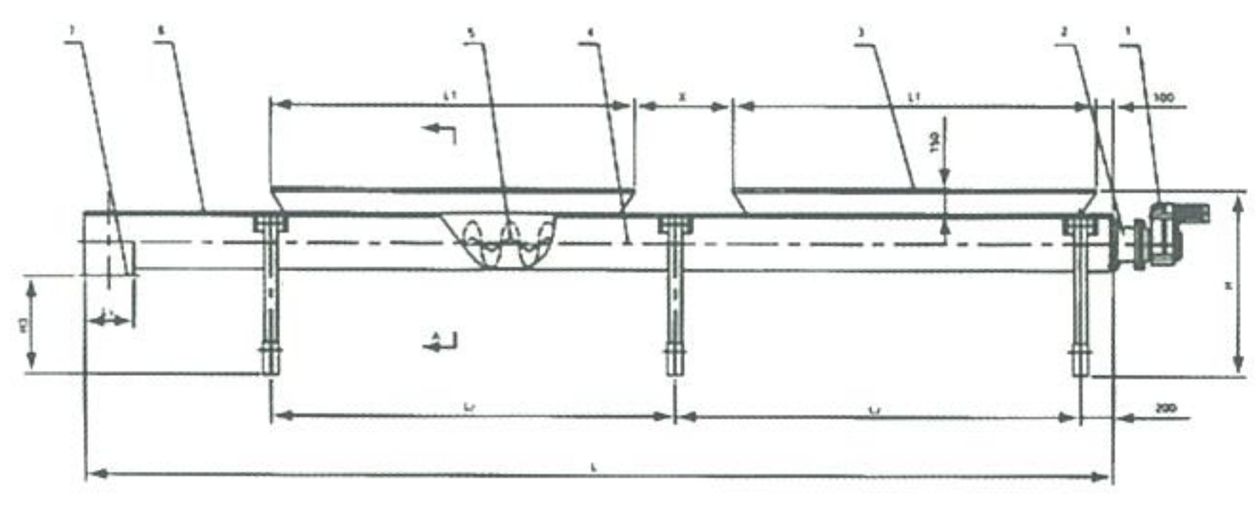
Key Installation Notes
- Conveyor length L is matched to the upstream screening or dewatering equipment
- Installation angle α: 0° (horizontal) to 20° (inclined) — capacity decreases with angle
- Inlet positioned directly below the discharge port of the upstream equipment
- Discharge end aligned with waste collection bin or downstream conveyor
- Support leg height H₃ adjusted to match upstream equipment discharge height
- Bi-directional operation available by reversing motor rotation direction
Request A Quote
Or Technical Consultation
Tell us your required conveying capacity, installation angle, conveyor length, and the upstream equipment it will interface with — we’ll size the right model and provide a detailed proposal.