
Wedge Wire
Spiral Screen
Cleaner
An all-in-one fine screening solution combining solids interception, enclosed screw conveying, and compression dewatering in a single compact unit. Installed at 35° in the channel — ideal for municipal wastewater plants requiring fine screening from 6 to 12 mm.
What Is A Wedge Wire
Spiral Screen Cleaner?
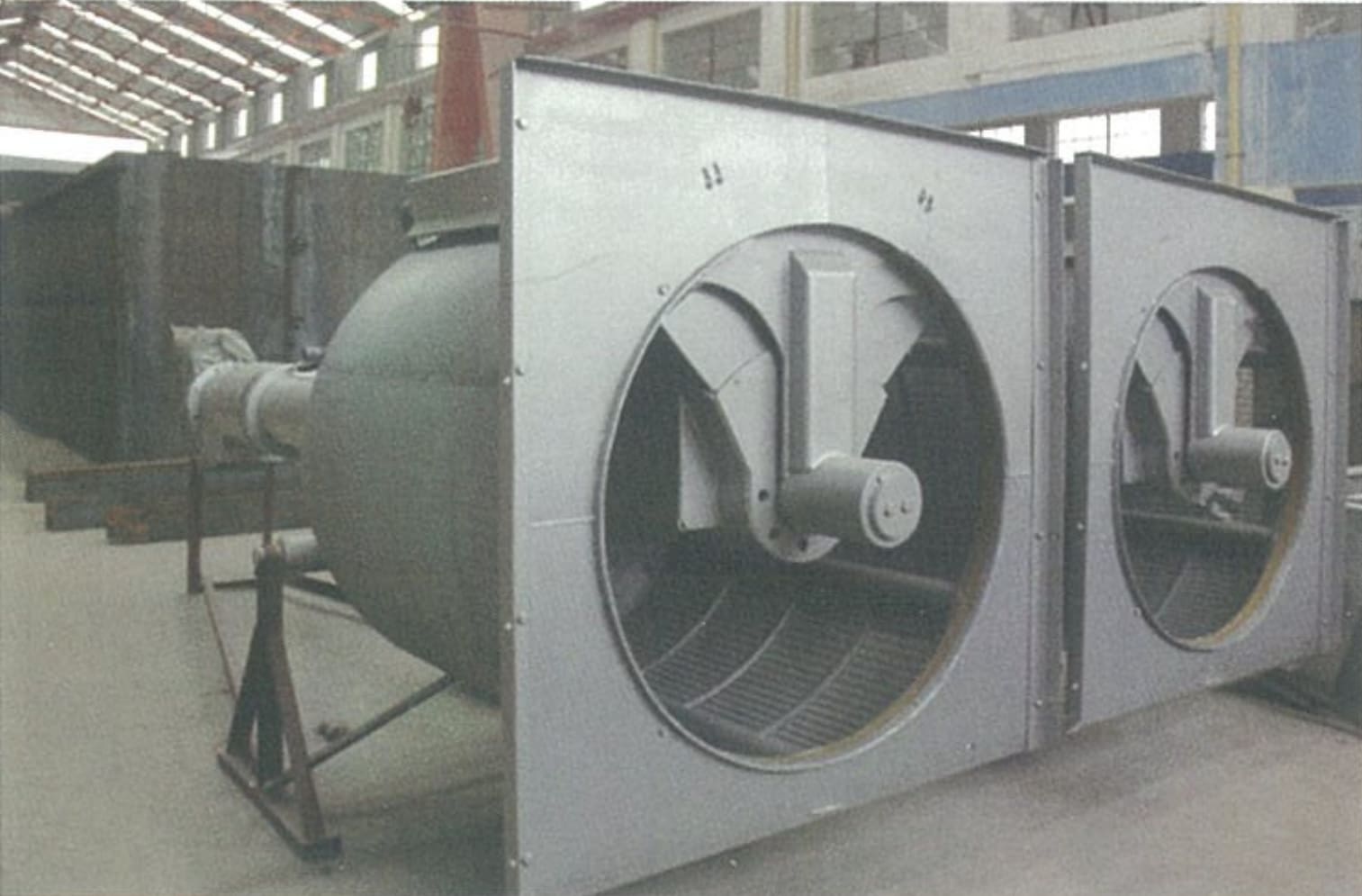
The Wedge Wire Spiral Screen Cleaner is a compact, all-in-one fine screening machine developed for municipal wastewater treatment plants. It integrates three functions — solids interception, enclosed screw conveying, and compression dewatering — into a single unit installed directly in the wastewater channel.
The cylindrical drum screen is formed by a series of circular wedge wire ring panels mounted at 35° to the horizontal. Wastewater enters the drum from the inlet head; solids larger than the bar spacing are retained on the inner screen surface. A toothed scraper blade, driven by the motor, rotates and sweeps retained screenings upward. As the motor reverses, the blade flips and a cleaning plate deposits the screenings into a collection trough. The screenings are then conveyed by a central screw, compressed, dewatered, and discharged from the outlet port into a collection bin or conveyor.
Self-cleaning operation during every cycle ensures the screen never blocks — even under high-solids loading conditions typical of fine screening applications.
- Municipal wastewater treatment plant fine screening
- Secondary treatment protection (MBR, trickling filters)
- Food processing and beverage industry effluent
- Textile, tannery, and pulp & paper wastewater
- Industrial pre-treatment and process water screening
Why Choose Our
Wedge Wire Spiral Screen
Compact Footprint
Compact structure with a small installation area. Easy to install, operate, and maintain — a single unit replaces separate screen, conveyor, and dewatering equipment.
Fine Bar Spacing
Bar spacing of 6–12 mm captures fine solids that coarse screens miss — protecting downstream biological treatment, membranes, and pumps from clogging and wear.
Enclosed Conveying
Fully enclosed screw transport tube prevents odor release and contamination of the surrounding environment during screenings conveyance to the discharge point.
Full Automation
Fully automatic control — stable operation, low power consumption, and low noise. Adaptable to timed, level-differential, or manual actuation modes.
Self-Cleaning / Never Blocks
Automatic self-cleaning during every operating cycle eliminates clogging risk, even under high-solids loading conditions typical of fine wastewater screening.
High Capture Efficiency
Wedge wire V-profile geometry and precise slot control maximize solids capture while maintaining low hydraulic head loss across the screen face.
How It Works
Screen
Wastewater enters the drum from the inlet head. Solids ≥ bar spacing are retained on the inner wedge wire surface.
Scrape
Toothed scraper rotates and sweeps retained solids upward. Motor reverses; cleaning plate deposits screenings into collection trough.
Convey
Central screw transports screenings upward through the enclosed tube — clean, odor-free, and spill-free conveyance to the compression zone.
Dewater & Discharge
Compression zone squeezes moisture from screenings. Dewatered solids discharge from the outlet port into a collection bin or conveyor.
Technical Parameters &
Installation Dimensions
| Parameter | Model | –600 | –800 | –1000 | –1200 | –1400 | –1600 | –1800 | –2000 | –2200 | –2400 | –2600 |
|---|---|---|---|---|---|---|---|---|---|---|---|---|
| Equipment Width B (mm) | — | 600 | 800 | 1000 | 1200 | 1400 | 1600 | 1800 | 2000 | 2200 | 2400 | 2600 |
| Channel Width B₁ (mm) | — | 620 | 820 | 1020 | 1220 | 1440 | 1640 | 1840 | 2040 | 2240 | 2440 | 2640 |
| Bar Spacing b (mm) | 6 ~ 12 | |||||||||||
| Installation Angle α (°) | 35 | |||||||||||
| Channel Depth H (mm) | H₃ + 300 ~ 500 | |||||||||||
| Discharge Height H₁ (mm) | 1,000 ~ 1,500 | |||||||||||
| Drum Speed n (r/min) | ≈ 6 | |||||||||||
| Motor Power N (kW) | 1.1 | 1.5 | 2.2 | |||||||||
| Overall Length L (mm) | b = 6 | 820 | 1010 | 1190 | 1400 | 1660 | 1870 | 2280 | 2490 | 2670 | 2990 | 3050 |
| b = 10 | — | 1010 | 1190 | 1400 | 1660 | 1880 | 2280 | 2490 | 2670 | 2900 | 3050 | |
| Screen Length L₁ (mm) | b = 6 | 430 | 540 | 620 | 740 | 840 | 900 | 1260 | 1300 | 1340 | 1370 | 1490 |
| b = 10 | 460 | 550 | 630 | 750 | 850 | 950 | 1260 | 1300 | 1340 | 1370 | 1490 | |
| Conveyor Length L₂ (mm) | — | 500 | 650 | 700 | 800 | 900 | 1000 | 1100 | 1200 | 1300 | 1400 | 1600 |
| Platform Length L₃ (mm) | — | 1230 | 1420 | 1420 | 1310 | 1590 | 1590 | 1590 | 1520 | 1520 | 1520 | 1520 |
| Water Depth H₃ (mm) | — | 300 | 350 | 480 | 590 | 750 | 850 | 950 | 1150 | 1250 | 1400 | 1490 |
| Civil Load P₁ (kN) | — | 7.2 | 8.3 | 10.4 | 11.76 | 19.5 | 22.0 | 25.0 | 38.0 | 41.0 | 46.0 | 56.0 |
| Civil Load P₂ (kN) | — | 3.5 | 4.1 | 5.2 | 5.8 | 9.75 | 11.0 | 12.2 | 18.7 | 20.4 | 22.9 | 27.9 |
| Note: P is calculated at H = 5.0 m. For each additional 1 m in H, total load P = P₁ (or P₂) + ΔP. | ||||||||||||
Flow Rate Table
| Parameter | Model | –600 | –800 | –1000 | –1200 | –1400 | –1600 | –1800 | –2000 | –2200 | –2400 | –2600 |
|---|---|---|---|---|---|---|---|---|---|---|---|---|
| Upstream Water Depth H₃ (mm) | — | 300 | 350 | 480 | 590 | 750 | 850 | 950 | 1150 | 1250 | 1400 | 1490 |
| Approach Velocity V’ (m/s) | 0.8 | |||||||||||
| Bar Spacing b (mm) |
6 | 83 | 130 | 200 | 300 | 419 | 630 | 850 | — | — | — | — |
| 10 | 91 | 151 | 241 | 346 | 482 | 638 | 878 | 1061 | 1315 | 1750 | 2150 | |
| Flow rate Q (m³/h) — total flow capacity per unit. Approach velocity V’ = 0.8 m/s. — = not applicable for this model/spacing combination. | ||||||||||||
Installation Dimensions
& Components
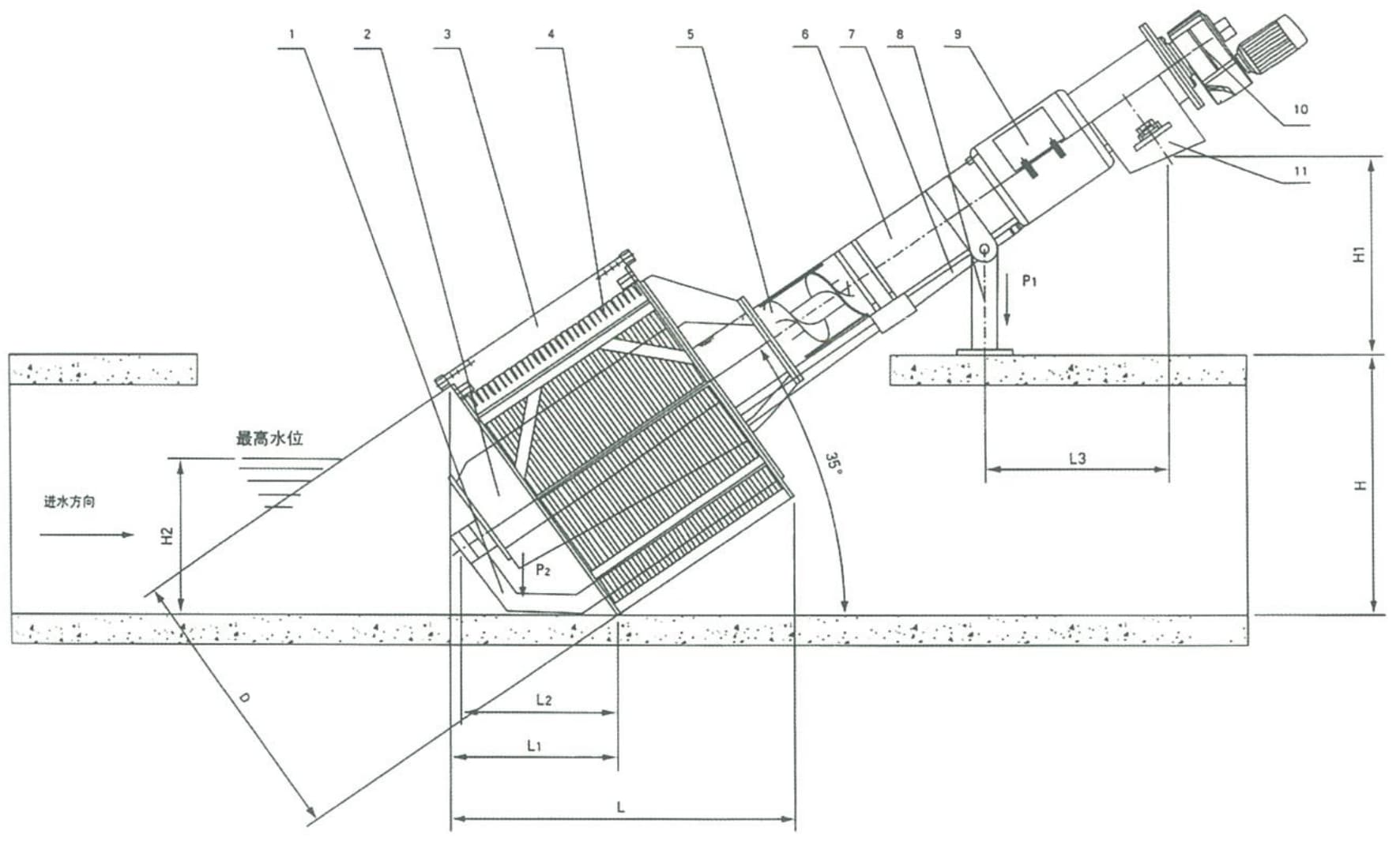
Key Installation Notes
- Fixed installation angle: 35° to horizontal
- Wastewater enters from the inlet head end of the drum
- Channel depth H = upstream water depth H₃ + 300 ~ 500 mm
- Discharge height H₁: 1,000 ~ 1,500 mm above platform
- Return pipe (overflow return) directed back to channel inlet
- Ensure adequate platform clearance for maintenance access
Request A Quote
Or Technical Consultation
Tell us your channel dimensions, upstream water depth, bar spacing, and flow requirements — we’ll recommend the right model and provide a detailed proposal.