
Rotary Drum
Screw Screen
A compact, all-in-one ultra-fine screening solution with a motor-driven rotating drum, integrated spray wash system, and central screw conveyor with compression dewatering. Bar spacing as fine as 1–5 mm — ideal for MBR protection and secondary treatment screening at municipal wastewater plants.
What Is A Rotary Drum
Screw Screen?
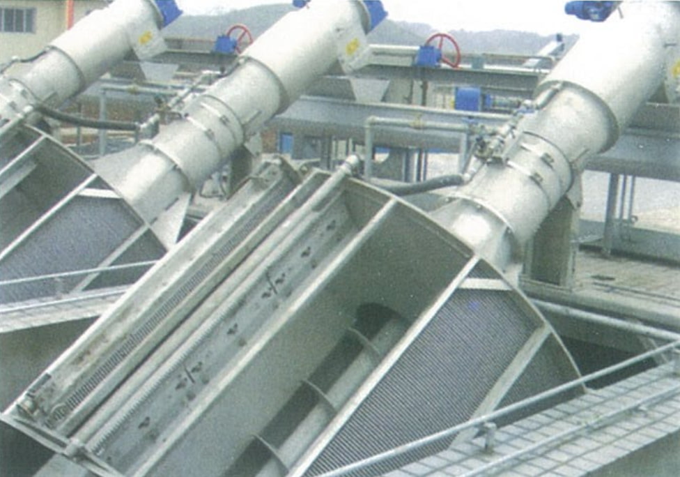
The Rotary Drum Screw Screen is a compact, all-in-one ultra-fine screening machine combining solids interception, drum rotation, spray washing, screw conveying, and compression dewatering in a single unit installed at 35° in the wastewater channel.
Unlike the Wedge Wire Spiral Screen where a fixed drum is cleaned by a rotating scraper, this machine features a motor-driven rotating cylindrical drum screen. Wastewater enters from the inlet head and flows inside the drum. Solids larger than the bar spacing are retained on the inner drum surface. As the entire drum rotates, a cleaning brush and spray wash mechanism mounted above the drum continuously flush the screen face, washing retained screenings down into a central collection hopper. The screw conveyor then transports, compresses, and dewaters the screenings before discharging them from the outlet port.
With bar spacing as fine as 1–5 mm, this unit is particularly suited for membrane bioreactor (MBR) protection and fine screening applications where the Wedge Wire Spiral Screen’s 6–12 mm opening is insufficient.
- Municipal wastewater ultra-fine screening (1–5 mm)
- Membrane bioreactor (MBR) pre-screening protection
- Secondary treatment and tertiary effluent polishing
- Food processing, beverage, and dairy effluent
- Textile, tannery, and pulp & paper wastewater
- Industrial pre-treatment for sensitive downstream processes
Why Choose Our
Rotary Drum Screw Screen
Ultra-Fine Screening
Bar spacing of 1–5 mm captures fine solids, fibers, and particles that coarser screens miss — essential for MBR membrane protection and advanced effluent polishing.
Rotating Drum + Spray Wash
The entire cylindrical drum rotates continuously. An overhead cleaning brush and spray wash system flush the screen face during every revolution — ensuring the drum never blocks.
Compact Footprint
Compact structure with a small channel installation area. Replaces separate screen, conveyor, and dewatering equipment in a single 35°-inclined unit.
Enclosed Screw Conveying
Fully enclosed screw transport and compression tube — odor-free, spill-free conveyance and dewatering of screenings before discharge.
Full Automation
Fully automatic control — stable operation, low power consumption, and low noise. Compatible with timed, level-differential, or manual actuation modes.
Self-Cleaning / Never Blocks
Automatic self-cleaning during every drum rotation cycle. Integrated spray wash eliminates clogging risk under high-solids ultra-fine screening conditions.
How It Works
Screen
Wastewater enters from the drum inlet head. Solids ≥ bar spacing are retained on the inner rotating drum surface.
Wash & Collect
Overhead brush and spray wash flush the rotating drum face. Screenings are washed into the central collection hopper below.
Convey
Central screw conveyor lifts screenings upward through the enclosed tube — clean, odor-free, and spill-free to the compression zone.
Dewater & Discharge
Compression tube squeezes moisture from screenings. Dewatered solids discharge from the outlet port to a bin or conveyor.
Technical Parameters &
Installation Dimensions
| Parameter | Model | –600 | –800 | –1000 | –1200 | –1400 | –1600 | –1800 | –2000 | –2200 | –2400 | –2600 |
|---|---|---|---|---|---|---|---|---|---|---|---|---|
| Equipment Width B (mm) | — | 600 | 800 | 1000 | 1200 | 1400 | 1600 | 1800 | 2000 | 2200 | 2400 | 2600 |
| Channel Width B₁ (mm) | — | 620 | 820 | 1020 | 1220 | 1440 | 1640 | 1840 | 2040 | 2240 | 2440 | 2640 |
| Bar Spacing b (mm) | 1 ~ 5 | |||||||||||
| Installation Angle α (°) | 35 | |||||||||||
| Channel Depth H (mm) | H₃ + 300 ~ 500 | |||||||||||
| Discharge Height H₁ (mm) | 1,000 ~ 1,500 | |||||||||||
| Drum Speed n (r/min) | ≈ 6 | |||||||||||
| Motor Power N (kW) | 1.1 | 1.5 | 2.2 | |||||||||
| Overall Length L (mm) | — | 860 | 1100 | 1340 | 1580 | 1810 | 2040 | 2280 | 2670 | 2700 | 3080 | 3410 |
| Screen Length L₁ (mm) | — | 330 | 450 | 560 | 660 | 780 | 910 | 1000 | 1120 | 1230 | 1350 | 1460 |
| Conveyor Length L₂ (mm) | — | 125 | 125 | 125 | 125 | 125 | 125 | 125 | 125 | 125 | 125 | 125 |
| Platform Length L₃ (mm) | — | 1230 | 1420 | 1420 | 1310 | 1590 | 1590 | 1590 | 1520 | 1520 | 1520 | 1520 |
| Water Depth H₂ (mm) | — | 400 | 520 | 670 | 800 | 930 | 1110 | 1230 | 1300 | 1500 | 1680 | 1750 |
| Civil Load P₁ (kN) | — | 6.6 | 7.7 | 9.8 | 11.0 | 18.7 | 21.0 | 23.4 | 26.1 | 36.6 | 40.4 | 45.0 |
| Civil Load P₂ (kN) | — | 3.3 | 3.86 | 4.9 | 5.5 | 9.4 | 10.5 | 11.7 | 13.1 | 18.3 | 20.2 | 22.3 |
| Note: P is calculated at H = 5.0 m. For each additional 1 m in H, total load P = P₁ (or P₂) + ΔP. | ||||||||||||
Flow Rate Table
| Parameter | Model | –600 | –800 | –1000 | –1200 | –1400 | –1600 | –1800 | –2000 | –2200 | –2400 | –2600 |
|---|---|---|---|---|---|---|---|---|---|---|---|---|
| Upstream Water Depth H₃ (mm) | — | 400 | 520 | 670 | 800 | 930 | 1110 | 1230 | 1300 | 1500 | 1680 | 1750 |
| Approach Velocity V’ (m/s) | 0.8 | |||||||||||
| Bar Spacing b (mm) |
1 | 36 | 60 | 100 | — | — | — | — | — | — | — | — |
| 2 | 54 | 90 | 154 | 214 | 306 | 402 | 510 | — | — | — | — | |
| 3 | 65 | 110 | 192 | 262 | 373 | 490 | 622 | 768 | 928 | 1104 | 1516 | |
| 4 | 68 | 120 | 203 | 280 | 402 | 572 | 756 | 930 | 1122 | 1300 | 1710 | |
| 5 | 70 | 130 | 224 | 310 | 400 | 616 | 815 | 1020 | 1213 | 1456 | 1840 | |
| Flow rate Q (m³/h) — total flow capacity per unit. Approach velocity V’ = 0.8 m/s. — = not applicable for this model/spacing combination. | ||||||||||||
Installation Dimensions
& Components
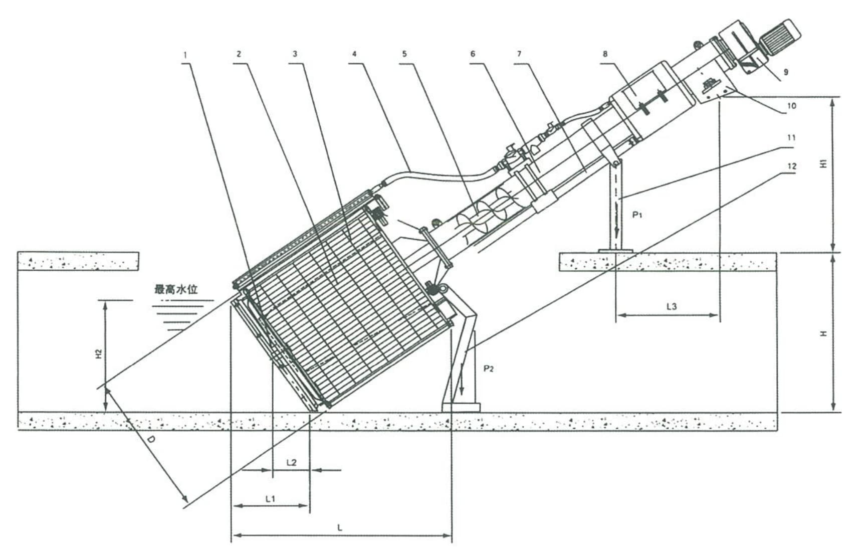
Key Installation Notes
- Fixed installation angle: 35° to horizontal
- Wastewater enters from the inlet head end of the rotating drum
- Channel depth H = upstream water depth H₃ + 300 ~ 500 mm
- Discharge height H₁: 1,000 ~ 1,500 mm above platform
- Spray wash water connection required at upper drum position
- Ensure adequate clearance above drum for brush and spray mechanism
Request A Quote
Or Technical Consultation
Tell us your channel dimensions, upstream water depth, required bar spacing, and flow requirements — we’ll recommend the right model and provide a detailed proposal.