
Triple-Wire-Rope
Grating
Cleaner
Heavy-duty wire-rope-driven bar screen cleaner for large-scale water intake facilities. Three-rope design with independent lift and flip drives handles deep channels and large floating debris loads with reliable, fully automated operation.
What Is A Triple-Wire-Rope
Grating Cleaner?
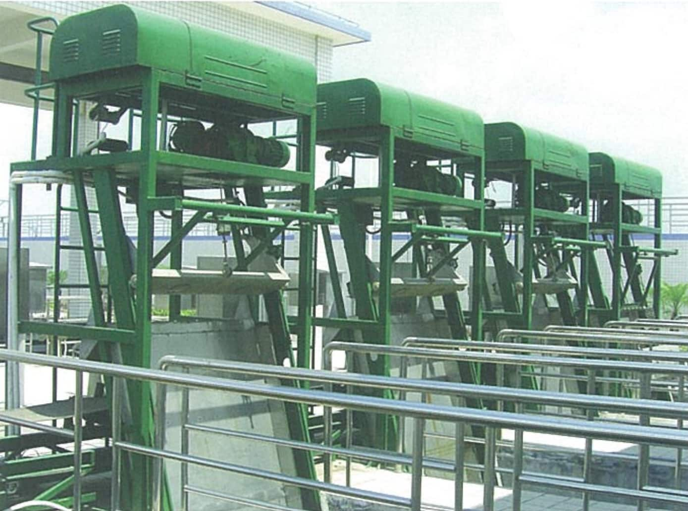
The Triple-Wire-Rope Grating Cleaner is a heavy-duty coarse screening machine designed for large water intake facilities. It features a split-frame construction: the upper machine frame is fixed at the wellhead, while the lower bar rack assembly forms the screening face independently.
When wastewater flows through the bar rack, solids larger than the bar spacing are retained. The rake bucket is first opened by the flip motor, then driven downward by the hoist motor along guide rails on both sides. Under height-limiter control, the bucket descends to the base of the screen pit, closes to capture debris, and is hoisted back up along the screen face and debris baffle. At the discharge point, a scraper blade mounted on the upper frame automatically strips the debris from the bucket and deposits it onto a conveyor or collection cart — completing one full cleaning cycle.
The three-rope system — two lateral guide ropes and one control rope — ensures smooth, stable bucket travel even in deep, wide channels where chain-driven systems are impractical.
- Large municipal water supply plant intakes
- Stormwater and sewage pump stations
- Wastewater treatment plant inlet screens
- Power plant cooling water intakes
- River and reservoir intake structures
Unlike chain-driven bar screens, the triple-wire-rope design is suited for very deep installations (up to 12,000 mm) and wide channels (up to 3,000 mm) where rigid chain systems would be too heavy or impractical. The wire-rope tensioning system also allows the bucket to handle large, bulky debris loads without jamming.
Why Choose Our
Triple-Wire-Rope Grating Cleaner
Split-Frame Design
Upper machine frame and lower bar rack assembly are independent — allowing separate installation, maintenance, and replacement without disrupting the full structure.
Heavy-Duty Grab Bucket
Large-capacity, heavy-duty “grab-type” rake bucket guided by roller wheels on both sides and wire-rope traction — stable and smooth even under heavy debris loads.
Auto Discharge Scraper
A scraper blade mounted on the upper frame automatically strips debris from the bucket at the discharge point — ensuring complete, hands-free debris removal every cycle.
Dual Independent Drives
Hoist motor (lift/lower) and flip motor (open/close bucket) operate as two fully independent systems under programmable electrical control.
Local / Remote Control
Simple, direct on-site operation or full remote control capability — adaptable to automated plant control systems.
Deep-Channel Capable
Suitable for channel depths up to 12,000 mm and widths up to 3,000 mm — well beyond the range of conventional chain-driven bar screen cleaners.
How It Works
Open & Lower
Flip motor opens the rake bucket. Hoist motor lowers it along guide rails to the base of the screen pit.
Close & Capture
Flip motor closes the bucket, engaging bar gaps and capturing retained debris from the screen face.
Hoist & Lift
Hoist motor raises the loaded bucket along the screen face and debris baffle to the discharge height.
Discharge & Reset
Scraper blade strips debris from bucket into collection bin. Cycle resets automatically for continuous operation.
Technical Parameters &
Installation Dimensions
| Parameter | Model | –1000 | –1100 | –1200 | –1300 | –1400 | –1500 | –1600 | –1700 | –1800 | –2000 | –2500 | –3000 |
|---|---|---|---|---|---|---|---|---|---|---|---|---|---|
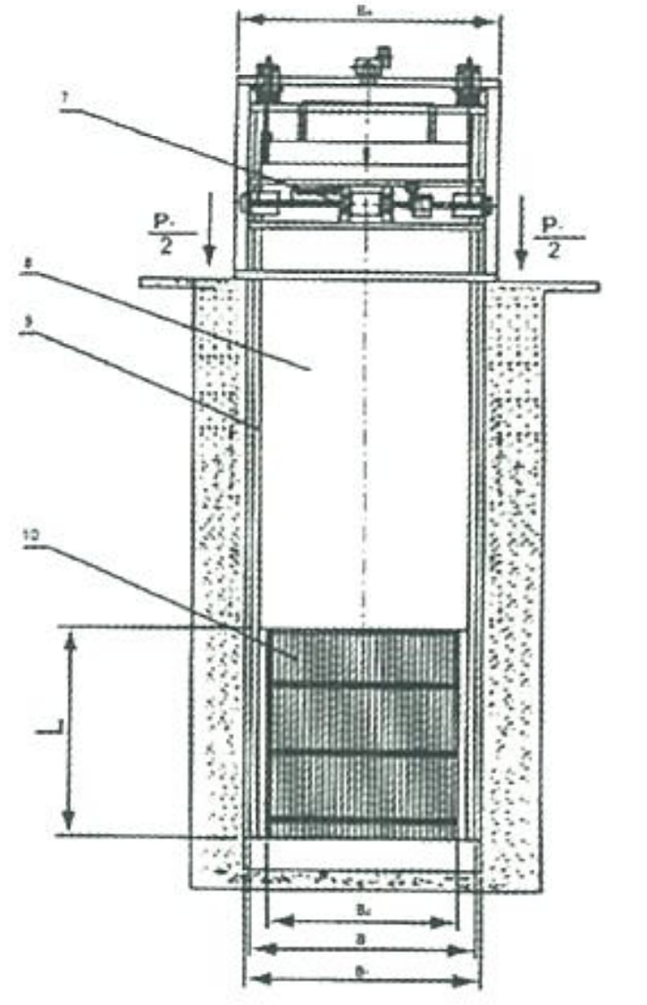
| Equipment Width B (mm) | — | 1000 | 1100 | 1200 | 1300 | 1400 | 1500 | 1600 | 1700 | 1800 | 2000 | 2500 | 3000 |
| Channel Width B₁ (mm) | B + 100 | ||||||||||||
| Effective Grid Width B₂ (mm) | B − 130 | ||||||||||||
| Foundation Bolt Spacing B₃ (mm) | B + 200 | ||||||||||||
| Total Equipment Width B₄ (mm) | B + 340 | ||||||||||||
| Bar Spacing b (mm) | 20 ~ 100 | ||||||||||||
| Installation Angle α (°) | 75 ~ 90 | ||||||||||||
| Channel Depth H (mm) | ≤ 12,000 | ||||||||||||
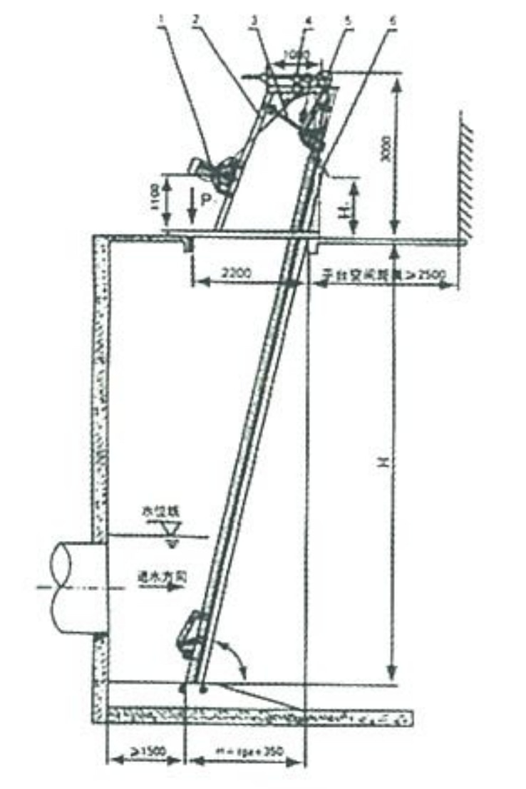
| Discharge Height H₁ (mm) | 1,000 ~ 1,200 | ||||||||||||
| Bar Length L (mm) | (Max. water depth + 600) / sinα (per client requirement) | ||||||||||||
| Bucket Travel Speed V (m/min) | ≤ 6.0 | ||||||||||||
| Hoist Motor Power N₁ (kW) | 1.1 ~ 2.2 | 1.5 ~ 3.0 | |||||||||||
| Flip Motor Power N₂ (kW) | 0.55 ~ 0.75 | 0.75 ~ 1.1 | |||||||||||
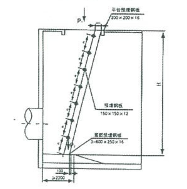
| Embedded Plates per Side n | n = H ÷ sinα ÷ 1000 (w ≥ 2) | ||||||||||||
| Civil Load | P₁ (kN) | 20.0 | 30.0 | ||||||||||
| P₂ (kN) | 15.0 | 20.0 | |||||||||||
| ΔP (kN) | 2.5 | ||||||||||||
| Note: P is calculated at H = 5.0 m. For each additional 1 m in H, total load P = P₁ (or P₂) + ΔP. | |||||||||||||
Flow Rate Table
| Parameter | Model | –1000 | –1100 | –1200 | –1300 | –1400 | –1500 | –1600 | –1700 | –1800 | –2000 | –2500 | –3000 |
|---|---|---|---|---|---|---|---|---|---|---|---|---|---|
| Upstream Water Depth H₃ (m) | 2.0 | ||||||||||||
| Approach Velocity V’ (m/s) | 0.8 | ||||||||||||
| Bar Spacing b (mm) |
20 | 0.87 | 0.97 | 1.07 | 1.17 | 1.27 | 1.37 | 1.47 | 1.57 | 1.67 | 1.87 | 2.36 | 2.86 |
| 30 | 0.98 | 1.09 | 1.20 | 1.31 | 1.42 | 1.54 | 1.65 | 1.76 | 1.87 | 2.10 | 2.66 | 3.22 | |
| 40 | 1.04 | 1.16 | 1.28 | 1.40 | 1.52 | 1.64 | 1.76 | 1.88 | 2.00 | 2.24 | 2.84 | 3.43 | |
| 50 | 1.08 | 1.21 | 1.33 | 1.46 | 1.58 | 1.71 | 1.82 | 1.96 | 2.08 | 2.33 | 2.95 | 3.58 | |
| 60 | 1.12 | 1.24 | 1.37 | 1.50 | 1.63 | 1.76 | 1.88 | 2.01 | 2.14 | 2.40 | 3.04 | 3.68 | |
| 70 | 1.14 | 1.27 | 1.40 | 1.53 | 1.66 | 1.79 | 1.92 | 2.06 | 2.19 | 2.45 | 3.10 | 3.76 | |
| 80 | 1.16 | 1.29 | 1.42 | 1.56 | 1.69 | 1.82 | 1.95 | 2.09 | 2.22 | 2.49 | 3.15 | 3.82 | |
| 90 | 1.17 | 1.31 | 1.44 | 1.58 | 1.71 | 1.84 | 1.98 | 2.11 | 2.25 | 2.52 | 3.19 | 3.86 | |
| 100 | 1.18 | 1.32 | 1.46 | 1.59 | 1.73 | 1.86 | 2.00 | 2.14 | 2.27 | 2.54 | 3.22 | 3.90 | |
| Flow rate Q (m³/m) — flow per unit width of screen. Conditions: H₃ = 2.0 m, V’ = 0.8 m/s. | |||||||||||||
Installation Dimensions
& Components
Key Installation Notes
- Platform clearance space: ≥ 2,500 mm above wellhead
- Installation angle range: 75°–90°
- Embedded plates per side: n = H ÷ sinα ÷ 1000 (minimum 2)
- Platform embedded plate: 220×200×15 mm
- Lower embedded plate: 3×600×250×16 mm
- Minimum upstream distance: ≥ 1,500 mm
Request A Quote
Or Technical Consultation
Tell us your channel dimensions, depth, bar spacing, and flow requirements — we’ll recommend the right model and provide a detailed proposal.