
Rotary Drum
Microfiltration
Machine
A fully automatic, level-controlled drum screen microfilter for the continuous removal of fine suspended solids from municipal and industrial wastewater — featuring integrated high-pressure backwash, SS304/316 all-stainless construction, and unattended 24/7 operation.
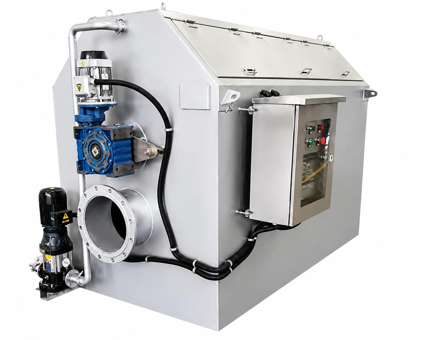
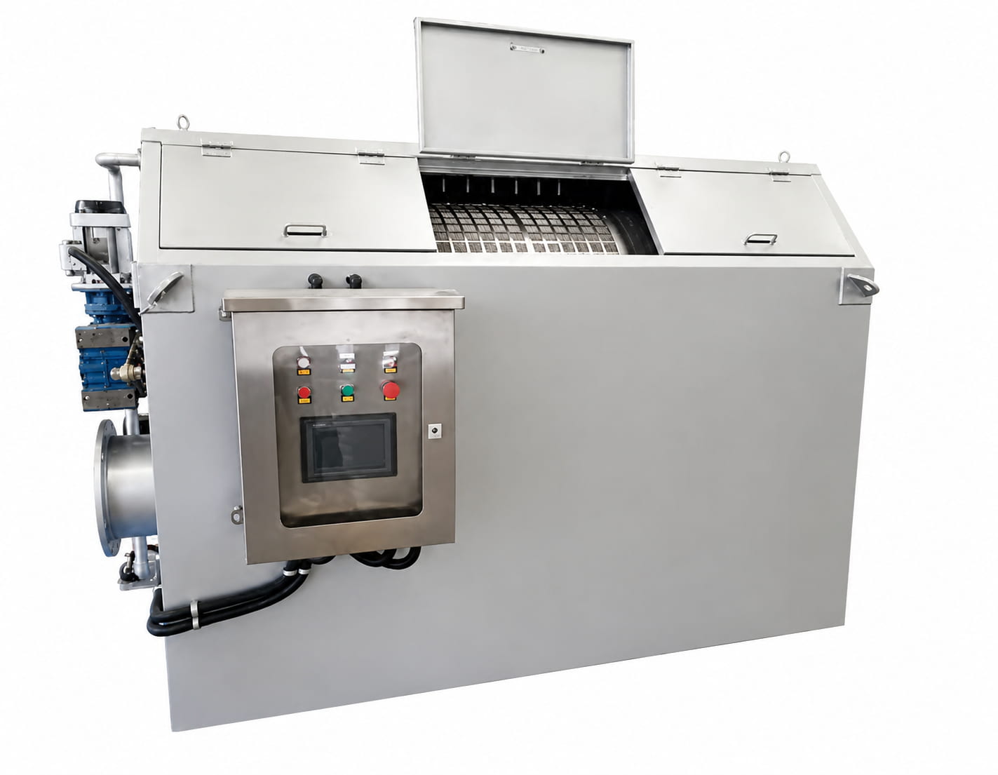
Automatic Fine-Screen
Microfiltration
The Rotary Drum Microfiltration Machine is an internally-fed rotating drum screen filter designed to remove fine suspended solids, fibres, and micro-particulates from water and wastewater streams. Wastewater enters the drum axially through the inlet and flows radially outward through a precision stainless steel screen panel — intercepting suspended solids on the inner drum surface while allowing the clarified filtrate to discharge through the base outlet to the next treatment stage or clear-water tank.
As retained solids accumulate on the screen surface, the water level inside the drum rises. When the level reaches the programmed high-water setpoint, the duckbill float switch activates simultaneously the backwash pump and the drum gear drive. High-pressure backwash water — delivered via a fixed nozzle manifold positioned outside the drum — flushes the accumulated solids inward and into the slag collection trough, from which they discharge through the sewage outlet. Once the screen is clean, the water level drops to the low-level setpoint, and the backwash cycle automatically stops. The unit then enters a new filtration cycle without operator input.
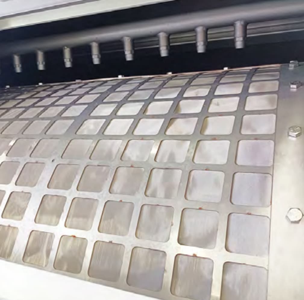
The entire machine housing is fabricated from 3 mm SS304 stainless steel plate, with a 1.2 mm inspection cover. The drum filter screen uses GKD 316 stainless steel wire mesh (imported) for outstanding corrosion resistance and long service life in aggressive wastewater environments.
- Municipal wastewater treatment — fine screening stage
- Industrial circulating water treatment (late-stage polishing)
- Aquaculture and fish farming recirculating systems (RAS)
- Paper and pulp mill fibre recovery
- Food and beverage processing wastewater
- Textile and printing dyeing wastewater pre-treatment
- Slaughterhouse and meat processing effluent
- Industrial wastewater requiring fine suspended-solids reduction
Three-Phase
Automatic Cycle
The microfiltration machine operates continuously through three repeating automatic phases, controlled entirely by the onboard float switch and level-sensing system — no operator attention required during normal service.
Engineering Features
Fully Unattended Operation
The level-based float switch system automatically initiates and terminates every backwash cycle in response to actual drum water level — not a fixed timer. This ensures the screen is cleaned exactly when needed and never over-washed, minimising water loss and eliminating the need for dedicated operator supervision.
GKD 316 Stainless Screen
The drum filter screen uses GKD 316 stainless steel wire mesh — a German-engineered precision woven screen with outstanding corrosion resistance, stable aperture geometry, and high mechanical strength. Screen gap ranges from 15 µm to 1 mm, selectable per application. The inverted-trapezoidal wire profile enhances self-cleaning during backwash and resists permanent blinding.
Shared-Pump Backwash System
The backwash pump can be configured to share duty with the facility’s existing lifting pump — eliminating the need and cost of a dedicated backwash pump. The anti-clog nozzle manifold uses pretreated effluent water as the backwash source, avoiding the consumption of fresh tap water and reducing the burden on the downstream treatment system.
Compact High-Capacity Design
The drum configuration delivers a large active filtration surface area within a minimal floor footprint. Units handle 100–200 m³/h of flow in a machine envelope of approximately 2.1–3.1 m × 1.58 m × 1.68 m — far smaller than equivalent capacity settling or DAF systems, with no civil work beyond a flat equipment pad.
All-Stainless SS304 Housing
The entire equipment shell is TIG-welded from 3 mm SS304 stainless steel sheet, with a 1.2 mm stainless steel inspection cover panel. All water-contact components — inlet/outlet tanks, trough, and drain pipework — are fully sealed and tested for zero leakage. The reducer is flange-mounted on the drum end via a torque-arm assembly for reliable, vibration-resistant drive.
In-Drum Concentration & Dewatering
Retained solids are not simply discharged — the drum’s internal structural design transports the captured material toward the slag outlet while progressively concentrating and partially dewatering it through the drum’s rotation. This reduces the volume of sludge discharged and lowers the moisture content of the solid fraction before it reaches the downstream sludge system.
Simple, Reliable Control Panel
The electrical control cabinet provides short-circuit and overload protection for all motor circuits via air circuit breakers, with thermal protection relays for the reducer and backwash pump motors. Auto/Manual mode switching allows manual override for maintenance. Protection grade IP55 as standard, suitable for outdoor installation with an optional weatherproof canopy.
Low Energy Consumption
The drum rotates slowly at 1–3 rpm under normal service conditions — the drive motor is only energised during backwash cycles. Total installed power is 1.5–2.25 kW depending on model, with actual running power draw significantly lower during the extended filtration phase. This delivers a highly favourable energy cost per cubic metre of treated water.
Configurable Screen Aperture
Screen mesh can be specified from 15 µm to 1 mm slot width at the time of order, and replacement screens of alternative apertures can be retrofitted in the field. This allows the same equipment frame to be re-optimised if feed water characteristics or downstream effluent requirements change after initial commissioning.
How It Works
Wastewater Inlet
Raw wastewater enters the drum axially through the flanged water inlet and distributes evenly across the inner drum surface via the inlet baffle structure.
Radial Filtration
Liquid passes radially outward through the fine stainless steel screen. Suspended solids larger than the screen aperture are retained on the inner drum surface.
Level Monitoring
As solids accumulate, screen permeability drops and water level inside the drum rises. The duckbill float switch monitors level continuously and triggers backwash at the set high-level point.
High-Pressure Backwash
The drum drive and backwash pump activate simultaneously. High-pressure water jets from the external nozzle manifold flush retained solids from the screen into the internal slag collection trough.
Solids Discharge
Concentrated solids exit the drum through the slag outlet and drain to the facility sludge system. Water level returns to the low-level setpoint, stopping the backwash cycle automatically.
Model Selection Table
| Model | Flow Capacity (m³/h) | Dimensions L×W×H (mm) | Drum Drive Power (kW) | Backwash Pump Power (kW) | Total Installed Power (kW) | Equipment Weight (T) |
|---|---|---|---|---|---|---|
| MS-GL-100 | 100 | 2122 × 1580 × 1675 | 0.75 | 0.75 | 1.50 | 0.80 |
| MS-GL-150 | 150 | 2660 × 1580 × 1675 | 0.75 | 1.10 | 1.85 | 0.85 |
| MS-GL-200 | 200 | 3140 × 1580 × 1675 | 0.75 | 1.50 | 2.25 | 0.94 |
| Notes: (1) Dimensions given are overall equipment envelope; installation clearance required per commissioning drawing. (2) Flange standard: GB/T 9119-2000. (3) Power supply: 380V / 3-phase / 50Hz. (4) Backwash pipe sizing determined per actual backwash pump selection. | ||||||
General Technical Parameters
| Parameter | Value / Specification |
|---|---|
| Drum Rotation Speed | 1–3 rpm (gear-driven, continuous during backwash) |
| Screen Aperture (slot width) | 15 µm – 1 mm (specified per order) |
| Screen Material | GKD 316 stainless steel woven wire mesh |
| Equipment Shell Material | SS304 (3 mm plate); inspection cover SS304 (1.2 mm plate) |
| Backwash Water Pressure | 0.2 – 0.3 MPa |
| Backwash Water Volume | 0.5% – 1.0% of production flow |
| Backwash Trigger | Duckbill float switch (high-level setpoint) |
| Backwash Stop | Float switch (low-level setpoint) — automatic |
| SS Removal Efficiency | > 80% of suspended solids at target screen aperture |
| Nozzle Connection — Water Inlet (a) | DN250 / RF flange (GB/T 9119-2000) |
| Nozzle Connection — Sewage Outlet (b) | DN80 / RF flange (GB/T 9119-2000) |
| Nozzle Connection — Filtered Water Outlet (c) | DN250 / RF flange (GB/T 9119-2000) |
| Power Supply | 380V / 3-phase / 50Hz |
| Control Panel Protection Grade | IP55 |
| Note: Performance data is based on typical municipal wastewater characteristics. Actual efficiency depends on incoming SS concentration, particle size distribution, and screen aperture selection. Technical datasheets and process sizing support available on request. | |
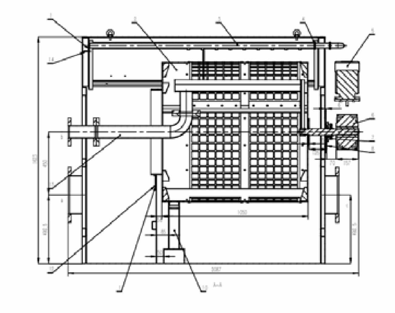
Equipment Structure
& Key Components
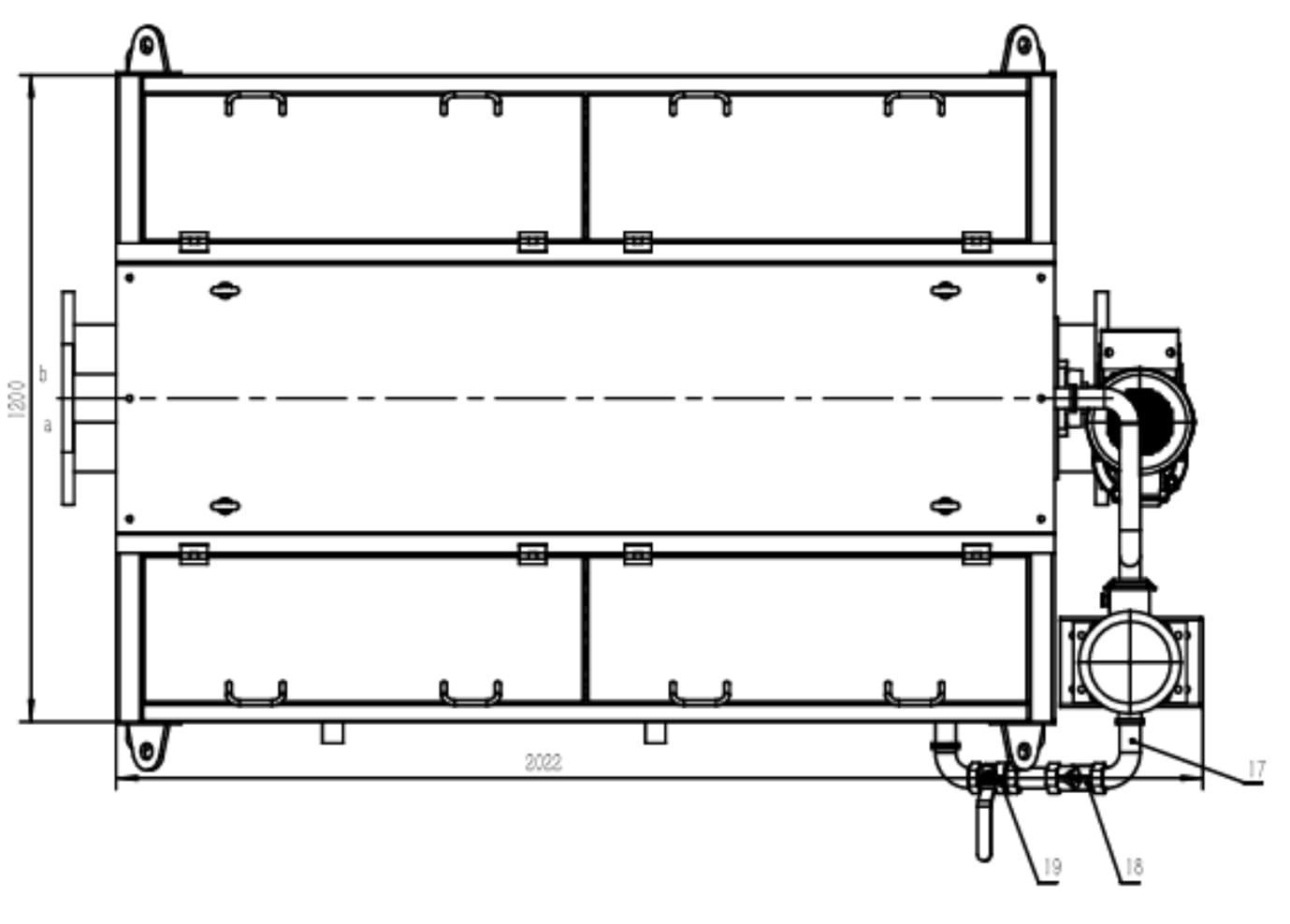
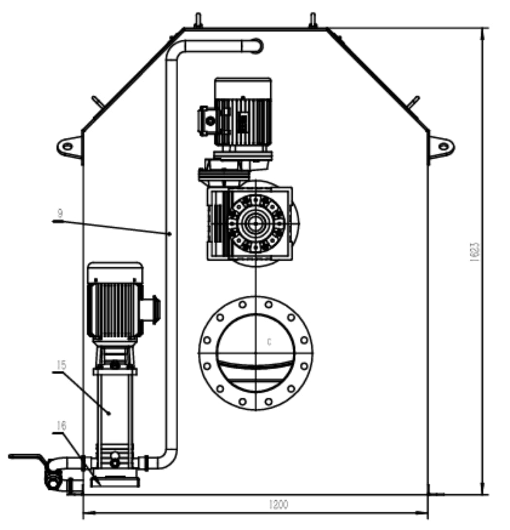
Installation & Commissioning Notes
- Mount on a flat, level concrete equipment pad — verify floor load rating against equipment weight (0.80–0.94 T) plus hydraulic head
- Inlet and outlet channels to be completely sealed to prevent leakage; test with clean water before commissioning
- Reducer is mounted on a torque-arm flange assembly — do not substitute with direct coupling without engineering review
- Backwash pipe sizing is determined by the actual backwash pump selected — confirm pump curve before finalising pipe diameter
- Ensure minimum 1 m access clearance on the control panel side and 0.6 m on the maintenance cover side
- Flush drum with clean water for 10 minutes before introducing process wastewater to remove assembly debris
- Check float switch operation manually before first automatic backwash cycle
Request A Quote
Or Technical Consultation
Tell us your design flow rate, feed water suspended solids concentration, and target effluent quality — we will recommend the right model and screen aperture for your application.