
Belt
Filter Press
A high-performance continuous sludge dewatering machine combining gravity thickening and mechanical pressing in one unit. Available in seven belt widths from 1,000 to 3,500 mm — high throughput up to 40 m³/h, low chemical and energy consumption, fully automatic operation with removable enclosure for clean, low-maintenance operation.
What Is The
Belt Filter Press?
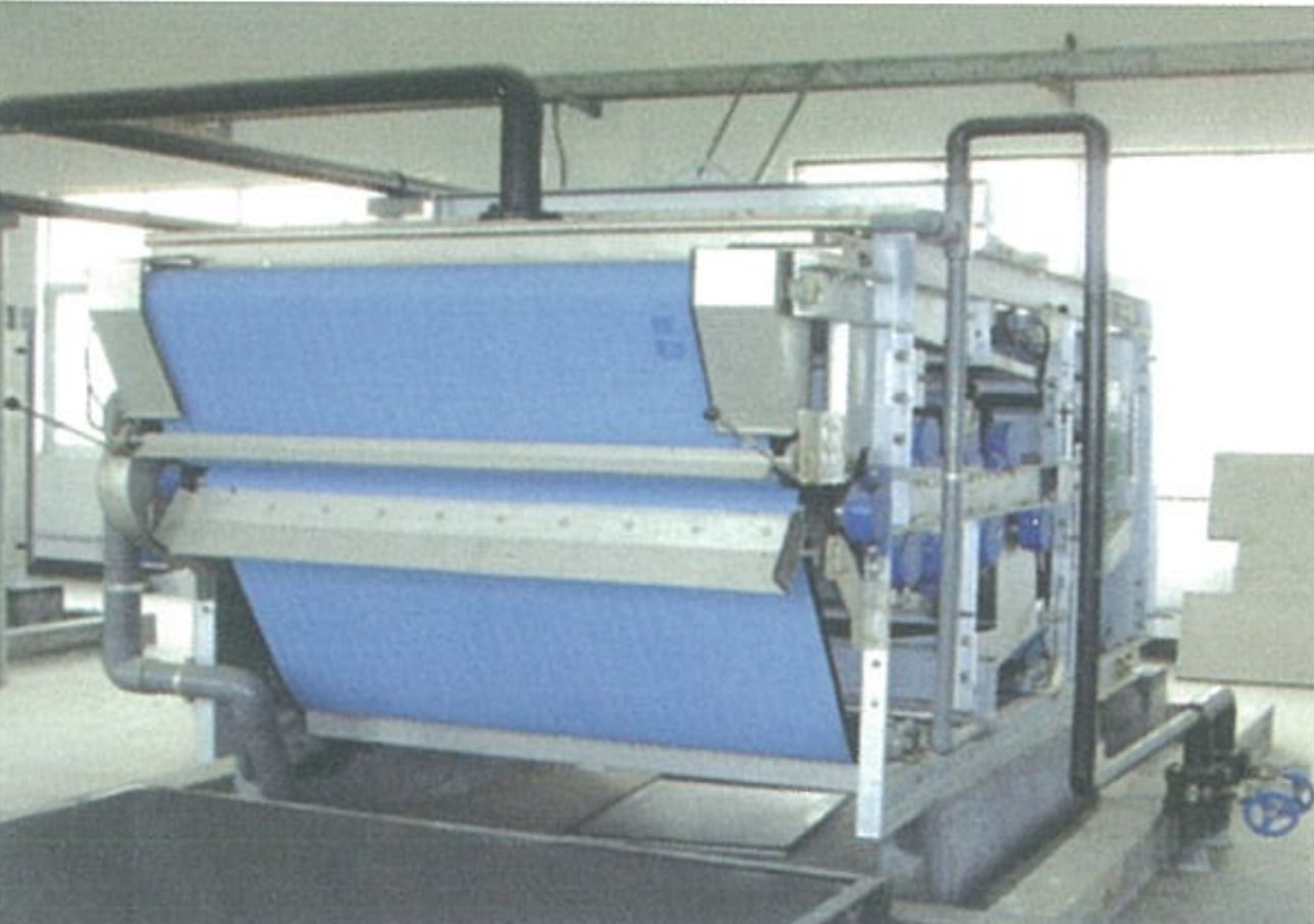
The Belt Filter Press is a high-performance continuous mechanical dewatering machine that integrates gravity thickening and belt pressing into a single compact unit. It is designed to deliver the best possible dewatering performance with high throughput, low chemical and energy consumption, clear filtrate, and high solids recovery.
Polymer-conditioned sludge enters through the inlet port and is spread evenly across the width of the gravity drainage zone, where free water drains through the lower filter belt under gravity. The thickened sludge is then progressively compressed in the wedge zone before entering the S-type multi-roller pressing zone, where upper and lower filter belts sandwich the sludge through rollers of decreasing diameter — applying increasing shear and compression force to extract the remaining water. The dewatered cake is discharged by scraper blades at the cake outlet. Both filter belts are continuously cleaned by a high-pressure spray wash system.
The machine features a removable enclosure — keeping the operating environment clean and hygienic while still allowing full maintenance access. Roller configurations of 6, 8, or 10 rollers are available to match sludge characteristics and required cake dryness.
- Municipal wastewater treatment plant biosolids
- Primary sludge and waste activated sludge (WAS)
- Anaerobically and aerobically digested sludge
- Industrial wastewater sludge — chemical, food, textile
- Paper & pulp, tannery, and dyeing industry sludge
- Mining, metallurgy, and coal washing slurry
Why Choose Our
Belt Filter Press
Best-in-Class Dewatering
High-performance dewatering system delivering optimal cake dryness. Thickening and pressing combined in one unit — achieving results equivalent to separate thickener plus press installations.
High Throughput
Capacity up to 40 m³/h (larger models). Continuous operation with belt speeds of 1.5–8.0 m/min — adjustable to balance throughput against desired cake dryness.
Low Chemical & Energy Cost
Optimized polymer conditioning and gravity pre-thickening reduce polymer consumption. Low drive motor power (1.5–4 kW) for a machine of this throughput capacity.
High Solids Recovery
Clear, low-turbidity filtrate. High solids capture efficiency minimizes solids returning to the treatment process via filtrate recycle — reducing overall plant load.
Fully Automatic Operation
Automated belt tensioning, belt tracking correction, and wash water control. Simple to operate and maintain — minimal operator attention required during continuous dewatering runs.
Removable Enclosure
Panels are removable for maintenance while providing full enclosure during operation — clean, hygienic working environment, odor containment, and protection of operators.
6 / 8 / 10 Roller Configuration
Roller count selectable to match sludge characteristics and required cake dryness — more rollers provide longer pressing time and drier cake output for difficult sludge types.
Auto Belt Tracking
Pneumatic belt alignment system automatically corrects belt drift during operation, ensuring consistent dewatering across the full belt width and preventing belt damage.
Continuous Belt Wash
High-pressure spray wash bars (≥ 0.5 MPa) continuously clean both filter belts after cake discharge — preventing blinding and maintaining stable filtration performance throughout operation.
How It Works
Gravity Drain
Polymer-conditioned sludge spreads across the lower belt. Free water drains by gravity, thickening the sludge from 1–5% to 10–15% DS.
Wedge Zone
Upper belt converges onto the sludge, gently leveling and pre-compressing it before the high-pressure roller section.
S-Type Pressing
Sludge is sandwiched between belts through decreasing-diameter rollers in an S-path — applying progressive shear and compression to squeeze out remaining water.
Cake Discharge
Doctor blades strip the dewatered cake from both belts. Belts are spray-washed clean before returning to the inlet for the next cycle.
Technical Parameters
| Parameter | SD1000 | SD1200 | SD1500 | SD2000 | SD2500 | SD3000 | SD3500 |
|---|---|---|---|---|---|---|---|
| Belt Width (mm) | 1,000 | 1,200 | 1,500 | 2,000 | 2,500 | 3,000 | 3,500 |
| Belt Speed (m/min) | 1.5 – 8.0 (adjustable) | ||||||
| Drive Motor Power (kW) | 1.5 | 1.5 | 2.2 | 2.2 | 3 | 3 | 4 |
| Wash Water Consumption (m³/h) | 3–5 | 6–10 | 9–15 | 12–20 | 15–25 | 18–30 | 22–35 |
| Wash Water Pressure (MPa) | ≥ 0.5 | ||||||
| Machine Weight — Empty (kg) | 2,500 | 3,500 | 4,500 | 5,500 | 7,000 | 8,500 | 9,500 |
| Operating Weight (kg) | 2,800 | 4,000 | 5,250 | 6,500 | 8,250 | 9,300 | 11,500 |
| Overall Dimensions L×W×H (mm) | 4045×1310×1920 | 4045×1540×1920 | 4045×1810×1920 | 4045×3310×1920 | 4045×3310×1920 | 4045×3350×1920 | 4350×3850×2110 |
| Hydraulic Throughput (m³/h) | 3–9 | 8–12 | 10–14 | 14–18 | 15–20 | 17–23 | 20–26 |
| Note: Hydraulic throughput depends on feed sludge type, solids concentration, and polymer conditioning. Roller configuration (6 / 8 / 10 rollers) selected per sludge characteristics. Wash water DN40 connection. | |||||||
Dimension Diagram
& Components
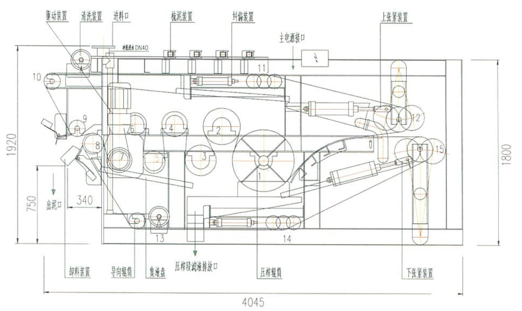
Key Installation Notes
- Wash water supply: DN40 connection, minimum pressure ≥ 0.5 MPa
- Sludge inlet port at top; cake outlet port on side (340 mm from end)
- Press-zone filtrate drain outlet at base of frame
- Filtrate collection pan (集液盘) integral to frame below pressing zone
- Adequate floor drainage required below the machine for filtrate and wash water
- Power supply: main power inlet at top of frame; check motor kW per model
Request A Quote
Or Technical Consultation
Tell us your sludge type, feed solids concentration, required throughput, and target cake dryness — we’ll recommend the right model and roller configuration for your application.