
Grit
Classifier
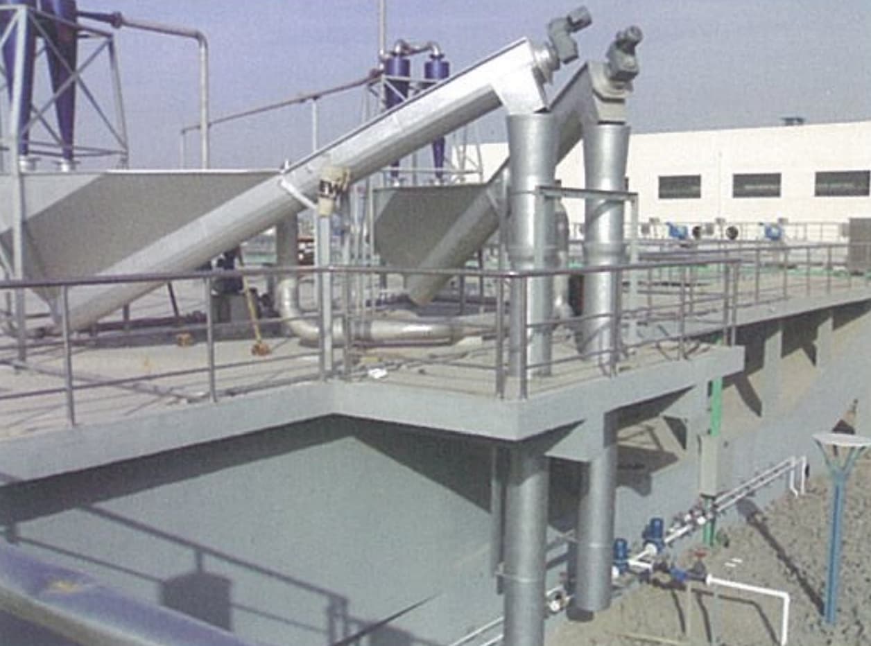
A shaftless screw grit classifier designed to receive grit-water slurry from cyclonic grit chambers or bridge-type suction grit removers, separate grit from water by gravity settling, and convey clean, dewatered grit to the collection bin — all in a fully enclosed, low-maintenance unit.
What Is A
Grit Classifier?
The Grit Classifier (砂水分离器) is a shaftless screw dewatering and classification machine used at municipal wastewater treatment plant grit removal stages. It receives grit-water slurry discharged from cyclonic grit chambers or bridge-type suction grit removers and separates the grit from the carrier water before disposal.
Grit-water slurry enters the unit from the top inlet of the separation trough. Grit particles settle by gravity to the bottom of the trough while the separated water overflows from the overflow outlet. The shaftless screw — driven by a shaft-mounted helical gear reducer — rotates at a low speed of approximately 4.8 r/min, progressively pushing the settled grit along the inclined U-trough (installed at 25°) toward the discharge outlet at the upper end. The dewatered grit falls into the collection bin for transport.
The fully enclosed design eliminates splashing and odor release, while the shaftless screw eliminates intermediate bearings — significantly reducing maintenance requirements compared to shafted classifier designs.
- Matched with cyclonic grit chambers at municipal WWTP
- Matched with bridge-type suction grit removers
- Aerated grit chamber grit dewatering
- Industrial wastewater grit classification and dewatering
- Stormwater and combined sewer grit handling
Why Choose Our
Grit Classifier
Shaft-Mounted Helical Gearbox
Drive unit uses a shaft-mounted parallel-axis helical gear reducer — compact, smooth, and stable in operation. No separate coupling between motor and screw.
High Grit Recovery
Recovery rate ≥ 96% for grit particles ≥ 0.2 mm diameter. Gravity settling in the separation trough combined with slow screw conveyance ensures high capture of the target grit fraction.
Wear-Resistant U-Trough Liner
U-trough fitted with replaceable wear liner — high abrasion resistance against grit particles, long service life, and easy replacement without removing the spiral.
Fully Enclosed Operation
Completely enclosed structure eliminates grit splashing and odor release during operation — cleaner working environment and better operator conditions at headworks.
No Pre-Embedded Civil Works
Frame anchored by expansion bolts directly to existing floor slab — no pre-embedded plates or cast-in anchors required. Reduces civil engineering cost and simplifies installation.
Low Moisture Discharge
Discharged grit moisture content < 65% — suitable for direct collection and transport without additional dewatering equipment downstream.
How It Works
Receive
Grit-water slurry from the grit chamber air-lift or suction pump enters the classifier from the top inlet of the separation trough.
Settle
Grit particles settle by gravity to the bottom of the separation trough. Separated water overflows from the overflow outlet and returns to the inlet channel.
Convey
Shaftless screw rotates at ≈ 4.8 r/min, pushing settled grit progressively up the 25° inclined U-trough toward the discharge end, further draining moisture along the way.
Discharge
Dewatered grit (moisture < 65%) falls from the discharge outlet into a collection bin or cart for transport and disposal.
Technical Parameters &
Installation Dimensions
| Parameter | –260 | –300 | –350 | –400 |
|---|---|---|---|---|
| Nominal Spiral Diameter D (mm) | 260 | 300 | 350 | 400 |
| Actual Spiral Diameter Φ (mm) | 235 | 285 | 320 | 385 |
| Capacity Q (m³/h) | 5–12 | 12–20 | 20–27 | 27–35 |
| Installation Angle α (°) | 25 | |||
| Spiral Speed n (r/min) | ≈ 4.8 | |||
| Motor Power N (kW) | 0.37 | 0.55 | 0.75 | |
| Grit Recovery (≥ 0.2 mm particles) | ≥ 96% | |||
| Discharge Moisture Content (%) | < 65 | |||
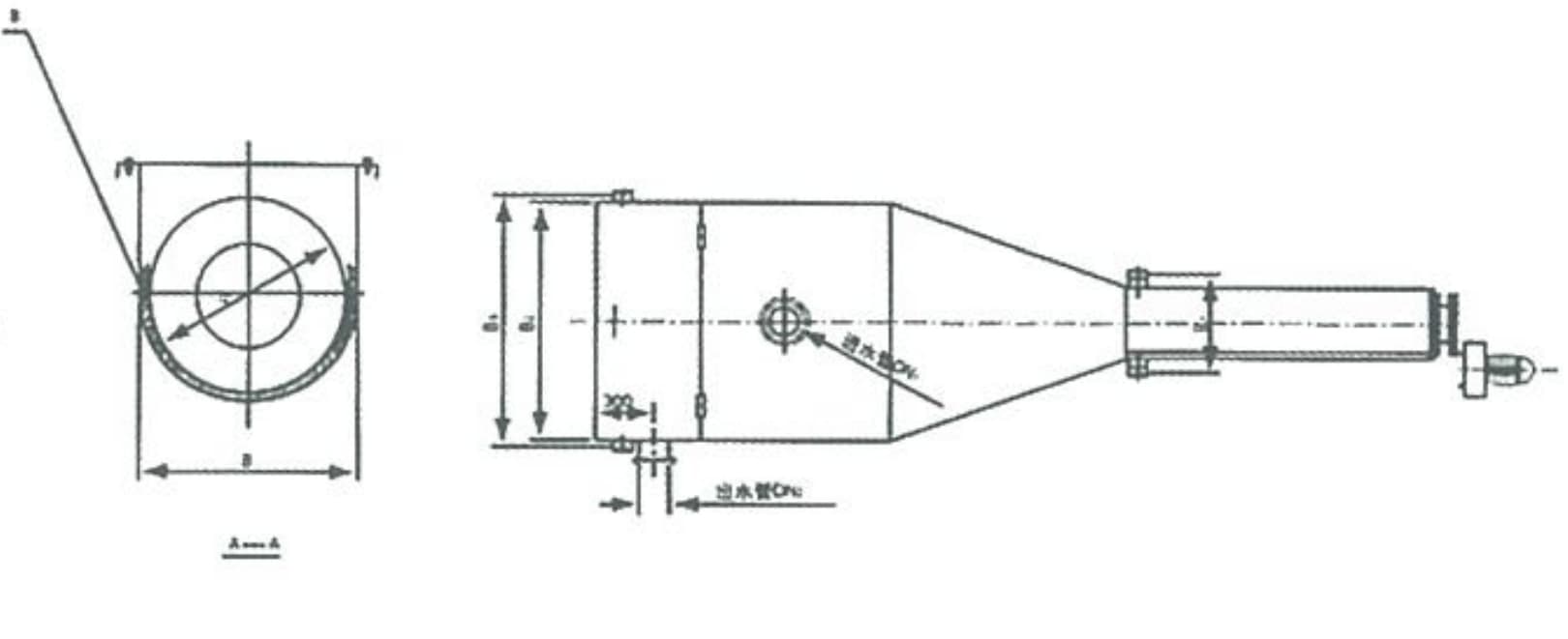
| ΦA — Trough Diameter (mm) | 220 | 270 | 320 | 390 |
| B — Trough Width (mm) | 260 | 310 | 345 | 410 |
| B₁ — Frame Width (mm) | 710 | |||
| B₂ — Overall Width (mm) | 1,200 | 1,360 | 1,500 | 1,800 |
| B₃ (mm) | B₂ + 80 | |||
| DN₁ — Inlet Pipe (mm) | 100 | 150 | 200 | 250 |
| DN₂ — Return Pipe (mm) | 150 | 200 | 250 | 300 |
| L — Screw Length (mm) | 2,800 | 3,000 | 3,200 | — |
| L₁ — Overall Length (mm) | 3,840 | 4,380 | 5,760 | 6,150 |
| L₂ — Base Length (mm) | 2,800 | 2,800 | 3,800 | 3,800 |
| H — Overall Height (mm) | 1,550 | 1,750 | 2,400 | 2,550 |
| H₁ — Inlet Height (mm) | 1,600 | 1,700 | 2,150 | 2,150 |
| Note: Frame fixed by expansion anchor bolts — no pre-embedded civil works required. DN₁ = grit slurry inlet; DN₂ = return water outlet back to inlet channel. | ||||
Installation Diagrams
& Components
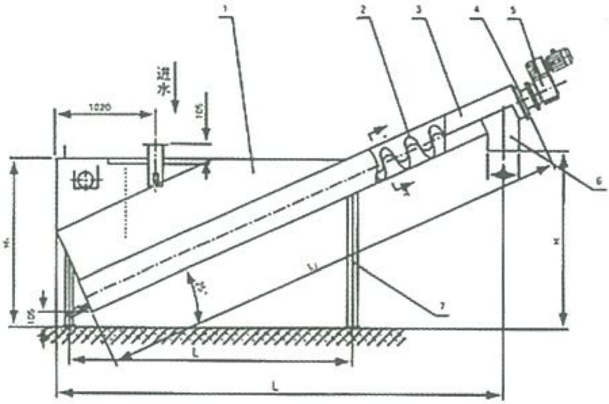
Key Installation Notes
- Installation angle: fixed at 25° to horizontal
- Frame anchored by expansion bolts — no pre-embedded plates required
- DN₁ inlet connects to air-lift riser pipe from grit chamber
- DN₂ return water outlet connects back to inlet channel or wet well
- Discharge end positioned above grit collection cart or bin
- Adequate floor drainage required below the separation trough
Request A Quote
Or Technical Consultation
Tell us your grit chamber model, grit slurry flow rate, and site conditions — we’ll select the right classifier model and provide a complete system proposal.