
Perforated
Rotary Drum
Screen
An automatic, self-cleaning externally-fed rotary drum screen for fine screening of municipal and industrial wastewater — from primary pre-treatment through to membrane bioreactor (MBR) protection. Stainless steel perforated media, continuous PLC-controlled operation, and an integrated intermittent spray-wash system.
Externally-Fed Fine
Drum Screening
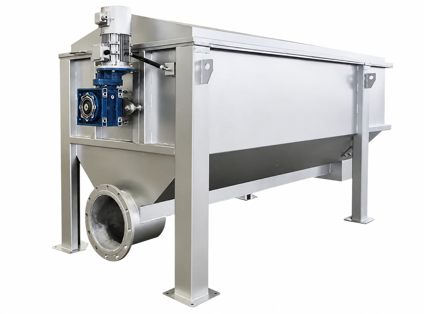
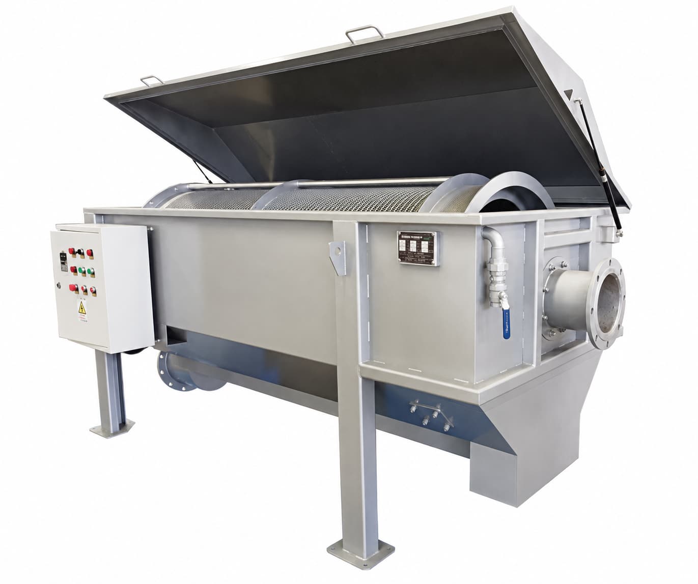
The Perforated Rotary Drum Screen is an externally-fed, continuously rotating fine screen designed for solid-liquid separation in primary, secondary, and tertiary wastewater treatment stages. Wastewater is fed via a distribution pipe onto the outer surface of the slowly rotating drum. Liquid flows inward through the perforated or wedge-wire screen panel and is discharged by gravity through the base outlet, while the captured screenings — fibres, suspended solids, and coarse particulates — remain on the drum exterior and are transported by the drum’s internal helical flights toward the solids discharge end.
A fixed external spray bar delivers timed high-pressure water jets across the full drum screening surface to dislodge captured material and restore screen permeability. The spray cycle frequency is fully adjustable via the PLC control panel to optimise cleaning performance against changing solids load. Because the spray wash system cleans the screen from the outside, it does not contaminate the filtered effluent — a significant operational advantage over internally-fed designs.
All structural components, the drum frame, and all wetted parts are available in SS304 or SS316 stainless steel. The drum is driven by a direct-coupled gearmotor — eliminating chain or belt transmissions and the associated maintenance overhead. Removable inspection covers on both sides provide full internal access for screen inspection, replacement, and routine servicing.
- Municipal wastewater treatment — primary and fine screening
- Membrane bioreactor (MBR) pre-screening protection
- Urban sewage lift stations and combined sewer overflow (CSO)
- Industrial wastewater — chemical, pharmaceutical, and food processing
- Oil field produced water and reinjection water filtration
- Circulating cooling water side-stream filtration
- Automobile manufacturing process water treatment
- Small and medium industrial factory effluent pre-treatment
Flexible Screen
Media Configuration
The filtering cylinder can be specified with three different screen media types to match the specific wastewater characteristics and required screening gap. All media are available in 304 or 316 stainless steel.
Perforated Plate
Punched stainless steel sheet with square or round apertures. High capture rate for particles larger than the opening size. Robust construction, suitable for high solids-load applications and coarser screening.
Stainless Wire Mesh
Woven SS wire mesh with small, closely-spaced apertures and low hydraulic resistance. High flow-rate characteristics retain fine suspended solids while maximising throughput capacity per unit drum area.
Wedge-Wire Profile
Triangular-profile wire screen with precisely controlled slot width. Self-cleaning wire geometry, minimal blinding tendency, and high mechanical strength — preferred for fibrous effluents and long-run operation.
Gap: 0.5–5 mm
Standard bar spacing of 1 mm suits most primary screening applications. Finer or coarser gaps are available to order — enabling the same drum frame to be re-equipped as process requirements evolve.
Why Choose This Screen
Primary to Membrane Grade
Handles the full range of fine screening duties — from primary pre-treatment of raw influent (removing rags, fibres, and grit-laden solids) through to tertiary fine screening before membrane bioreactors and other sensitive downstream processes. A single equipment platform covers multiple treatment stages with screen media selection.
Adjustable Intermittent Spray Wash
A fixed external spray bar with anti-clog nozzles washes the entire drum screening surface during each spray cycle. Cycle frequency and duration are independently programmable via the PLC — allowing the cleaning intensity to be matched to the actual solids loading rate and preventing unnecessary water consumption during periods of low influent turbidity.
Chain-Free Gearmotor Drive
The drum is driven directly by a flange-mounted gearmotor via a trunnion wheel support system — eliminating the chains, sprockets, and tension adjustment that are the primary maintenance burden of conventional drum screens. The result is a lower mean time between service interventions and a significantly reduced lifetime maintenance cost.
Internal Helical Flight Conveying
Non-continuous helical flights welded inside the drum transport the captured screenings axially toward the discharge end as the drum rotates. Screenings exit the drum cleanly by gravity into a post-screening compactor, bag press, or collection container — without requiring a separate conveyor or separate drive.
PLC Auto / Manual Operation
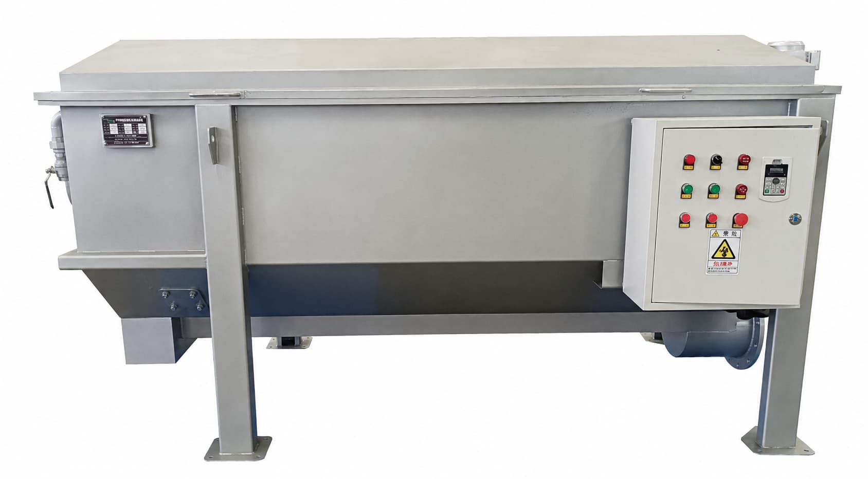
The onboard PLC panel manages drum rotation, spray cycle timing, and fault alarm outputs in either automatic (fully unattended) or manual (operator-directed) mode. Remote monitoring integration and VFD drum speed control are available as options, enabling flow-paced operation and SCADA connectivity for large plant installations.
Removable Inspection Covers
Full-width removable enclosure panels on both sides of the unit provide unobstructed internal access for screen inspection, screen panel replacement, and internal flight maintenance — without requiring drum removal or partial dismantling of the structural frame.
All-Stainless SS304 / 316
The entire support structure, drum frame, spray pipework, and all wetted parts are available in SS304 as standard and SS316 for aggressive chemical environments or marine applications. The fully stainless construction resists corrosion from hydrogen sulphide, aggressive process water chemistry, and continuous wash-water exposure over the equipment lifetime.
Optional Waste Compaction & Bagging
An optional compacting press and bag-filling system can be installed in the discharge zone. This reduces the volume of transported screenings waste, prevents odour migration from open skips, and simplifies compliance with waste disposal regulations — particularly important for screenings containing pathogenic material from municipal wastewater.
Compact Installation Profile
The horizontal drum configuration delivers a high active filtering area per unit of plant floor space, with a machine height of just 1.28–1.45 m. This suits low-headroom installations in existing plant rooms, underground chambers, or constrained site layouts where taller drum screen formats cannot be accommodated.
How It Works
Feed Distribution
Wastewater is pumped to the flow distribution pipe, which distributes the flow evenly along the full length of the drum outer surface, avoiding concentrated loading at any single point.
Drum Filtration
Liquid passes radially inward through the rotating perforated screen. Suspended solids, fibres, and particles larger than the screen gap are captured and retained on the outer drum surface as screenings.
Screenings Transport
Internal helical flights transport the captured screenings axially toward the discharge end of the drum as it rotates, progressively concentrating and partially dewatering the material during transit.
Spray Wash & Discharge
The PLC-timed external spray bar flushes retained solids from the screen surface. Screenings exit via the discharge outlet into a compactor or container. Treated filtrate discharges by gravity from the drum base outlet.
Model Selection Table
| Model | Bar Spacing (mm) | Flow Capacity (m³/h) | Dimensions L×W×H (mm) | Drive Power (kW) | Inlet Diameter | Outlet Diameter | Drum Diameter (m) | Weight (T) |
|---|---|---|---|---|---|---|---|---|
| MS-ZG-100 | 1 | 100 | 2270 × 1100 × 1275 | 0.75 | DN150 | DN250 | 0.75 | 0.59 |
| MS-ZG-150 | 1 | 150 | 2970 × 1300 × 1445 | 0.75 | DN200 | DN300 | 0.75 | 0.90 |
| MS-ZG-200 | 1 | 200 | 3570 × 1300 × 1445 | 0.75 | DN250 | DN350 | 0.75 | 1.25 |
| Notes: (1) Dimensions are overall equipment envelope; confirm installation clearances per commissioning drawing. (2) Bar spacing of 0.5–5 mm available on request. (3) SS316 construction available for corrosive service. (4) Optional waste compactor and bag-filling system available. | ||||||||
General Technical Parameters
| Parameter | Value / Specification |
|---|---|
| Feed Configuration | Externally fed — flow distributed onto outer drum surface |
| Screen Media Options | Perforated plate / stainless wire mesh / wedge-wire triangular profile |
| Standard Bar / Gap Spacing | 1 mm (0.5–5 mm range available per application) |
| Screen Material | SS304 standard; SS316 for corrosive service |
| Drum Drive System | Direct-coupled gearmotor with trunnion wheel support (chain-free) |
| Drum Rotation Speed | Low-speed continuous rotation (PLC-controlled) |
| Cleaning System | Fixed external spray bar with anti-clog nozzles; intermittent timed cycles |
| Spray Wash Cycle | Frequency and duration programmable via PLC |
| Screenings Conveying | Internal non-continuous helical flights — axial transport to discharge end |
| Treated Water Discharge | Gravity discharge from base of drum; no pump required |
| Control System | PLC panel; auto / manual switchable; fault alarm output |
| Power Supply | 380V / 3-phase / 50Hz (standard) |
| Structural Material | SS304 throughout (SS316 wetted parts available) |
| Note: Hydraulic performance subject to actual influent SS concentration and screen gap selection. Process sizing support and technical datasheets provided with quotation. | |
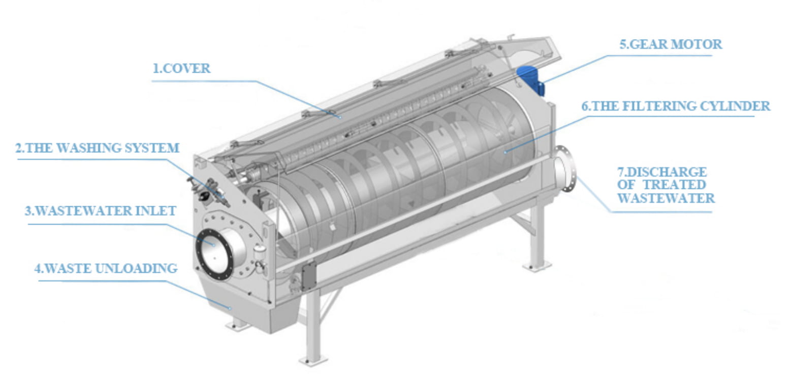
Equipment Structure
& Key Components
Installation & Commissioning Notes
- Unit is channel-mounted or pad-mounted; confirm sill or support beam level to within ±2 mm before anchoring
- Inlet pipe to connect to distribution manifold — ensure no surge flow that could exceed drum hydraulic capacity
- Spray wash water supply: minimum 0.3 MPa stable pressure; connect via Y-type strainer to protect nozzles
- Screenings discharge outlet to clear directly into compactor, skip, or bag-filling unit — avoid discharge drop exceeding 600 mm to prevent splashing
- Allow minimum 800 mm clearance on each side for inspection cover removal and internal access
- Commission PLC spray cycle timing with clean water before introducing process wastewater
- Verify gearmotor rotation direction against drum rotation arrow before first start-up
Request A Quote
Or Technical Consultation
Tell us your design flow rate, influent characteristics, and screening duty — we will recommend the right model, screen media, and gap size for your application.