
Biological
Odour Control
System
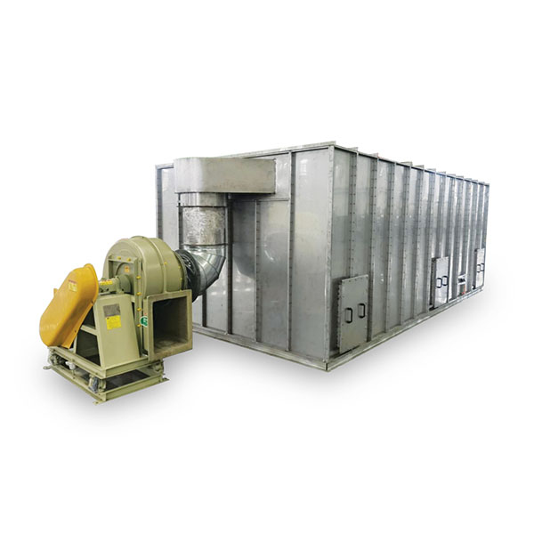
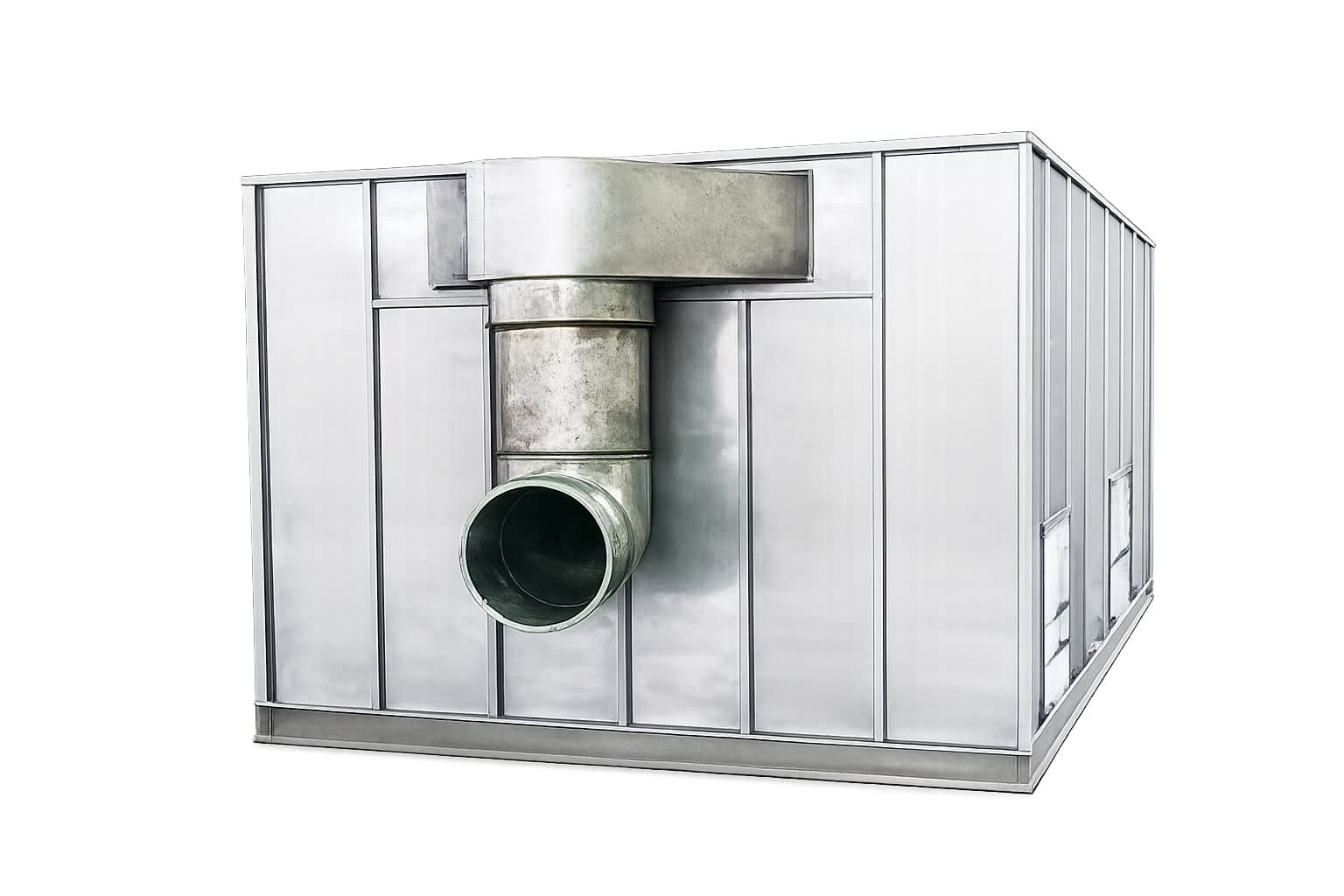
A fully enclosed biofilter system that uses microbial activity to convert hydrogen sulphide, ammonia, and volatile organic compounds into odourless, harmless end products — without chemicals, without secondary pollution.
Biotechnology-Based
Odour Treatment
The Biological Odour Control System harnesses the metabolic activity of specialised deodorising microorganisms inoculated onto a high-surface-area composite filter medium. By maintaining optimised humidity, pH, oxygen and nutrient conditions, odorous compounds are adsorbed, absorbed and biologically degraded into carbon dioxide, water and inorganic salts — entirely without chemical dosing.
The system is ideally suited for treating complex, mixed-composition malodorous gas streams with large volumetric flow rates. Its double-layer insulated enclosure, PLC automation and robust glass-fibre-reinforced plastic or stainless steel construction make it reliable across a wide range of climates and operating environments.
Key subsystems include a pre-washing bed, biological filter bed, circulating spray humidification network, gas collection and discharge ducting, and a parameter control panel. Ancillary instruments — pH transmitters, humidity sensors, temperature controllers and flow rotameters — are maintained on a scheduled basis to ensure stable, safe long-term operation.
- Municipal wastewater treatment plants (headworks, primary clarifiers, sludge processing)
- Sludge thickening, dewatering and drying facilities
- Sewage pump stations and underground wet wells
- Industrial wastewater pretreatment units (food, pharmaceutical, chemical)
- Composting and organic waste processing facilities
- Landfill leachate treatment plants
- Livestock and agricultural waste management sites
- Underground utility tunnels with H₂S accumulation risk
- Transfer stations and waste collection hubs
- Hydrogen sulphide (H₂S)
- Ammonia (NH₃) and amine compounds
- Mercaptans (methanethiol, ethanethiol)
- Volatile organic compounds (VOCs)
- Indole, skatole and other malodorous heterocyclics
- Mixed odour gases with fluctuating concentration (3–1,500 ppm)
Why Choose Biological
Odour Treatment
Zero Chemical Dosing
The biological process requires no acid, alkali, oxidiser or activated carbon. Operating costs are low and there is no risk of chemical handling hazards or secondary pollution from reagent discharge.
Multi-Pollutant Treatment
A single system simultaneously treats H₂S, NH₃, mercaptans, VOCs and mixed odour streams — eliminating the need for separate treatment trains for each compound class.
High Impact Resistance
The microbial community self-adapts to inlet concentration fluctuations between 3 and 1,500 ppm, maintaining stable purification performance without operator adjustment.
Rapid Purification
Residence time in the biofilter is only 5–10 seconds, enabling compact equipment footprints with high throughput. Overall deodorisation efficiency consistently exceeds 95%.
One-Time Inoculation
Biological strains are filmed onto the medium in a single inoculation step. Multiple species with complementary metabolic pathways are applied simultaneously, reducing start-up time and long-term maintenance burden.
Corrosion-Resistant Construction
Equipment shells are fabricated from glass fibre reinforced plastic (GRP) or stainless steel with a dedicated internal anti-corrosion lining, providing long service life in highly corrosive H₂S environments.
Cold-Climate Operation
The double-layer enclosure is filled with thermal insulation material between the inner and outer shells, maintaining optimum microbial operating temperature even in sub-zero ambient conditions.
High-Performance Filter Medium
Composite structured packing provides a large specific surface area with excellent air permeability. The medium resists compaction and hardening, delivering a long service life without replacement-driven downtime.
PLC Automated Control
A fully automated PLC panel monitors temperature, humidity, pH and flow in real time, activating spray, ventilation and alarm functions automatically to minimise operator intervention.
How The System Works
Gas Collection
Odorous air is captured at emission sources — process tanks, sludge handling areas, screen rooms — via negative-pressure ductwork and fan, preventing fugitive odour escape.
Pre-Washing
The collected gas passes through the washing bed where circulating water removes particulates, lowers temperature and dissolves highly soluble compounds such as NH₃, conditioning the gas for optimal biofilter performance.
Humidification
The spray humidification network maintains relative humidity at 95–100% inside the biofilter bed, creating the moist microenvironment required for microbial metabolic activity without flooding or channelling.
Biological Degradation
Odorous compounds diffuse into the biofilm on the filter medium surface. Specialised microorganisms oxidise H₂S to sulphate, nitrify NH₃ to nitrate, and metabolise organic malodourants to CO₂ and H₂O within 5–10 seconds.
Clean Air Discharge
Purified gas with odour removal exceeding 95% is discharged through the outlet to atmosphere. The PLC logs all process parameters continuously and triggers alarms if any setpoint is exceeded.
Model Selection Table
| Model | Air Capacity (m³/h) | Spray Water Volume (m³/h) | Dimensions L×W×H (mm) | Fan Power (kW) | Spray Pump Power (kW) | Humidification Pump Power (kW) | Installed Power (kW) | Empty Weight (T) | Full Load Weight (T) |
|---|---|---|---|---|---|---|---|---|---|
| MS-CC5000 | 5,000 | 14 | 5000×2590×3045 | 5.5 | 2.2 | 2.2 | 12.1 | 2.29 | 9.4 |
| MS-CC8000 | 8,000 | 16 | 6500×3090×3045 | 7.5 | 3.7 | 2.2 | 17.1 | 2.29 | 14.63 |
| MS-CC11000 | 11,000 | 22 | 8000×3590×3045 | 11 | 3.7 | 2.2 | 20.6 | 2.78 | 20.15 |
| MS-CC17000 | 17,000 | 34 | 10500×4090×3045 | 15 | 5.5 | 2.2 | 28.2 | 3.31 | 30.51 |
| MS-CC25000 | 25,000 | 50 | 14000×4590×3045 | 30 | 7.5 | 2.2 | 47.2 | 4.49 | 43.59 |
| MS-CC30000 | 30,000 | 60 | 15000×5090×3045 | 37 | 11 | 2.2 | 61.2 | 4.93 | 52.53 |
| MS-CC40000 | 40,000 | 80 | 17000×5590×3045 | 45 | 11 | 2.2 | 69.2 | 4.49 | 63.82 |
| Notes: (1) Dimensions are overall equipment envelope; site access and maintenance clearances to be confirmed per commissioning drawing. (2) Power supply: 380V / 3-phase / 50Hz. (3) Intermediate capacities and custom configurations available on request. (4) Weight figures are for standard GRP construction; stainless steel shell option adds approximately 15–20% to empty weight. | |||||||||
General Technical Parameters
| Parameter | Value / Specification |
|---|---|
| Inlet Odour Concentration | 3 – 1,500 ppm (H₂S equivalent) |
| Deodorisation Efficiency | > 95% (typical operating conditions) |
| Biological Residence Time | 5 – 10 seconds |
| Biofilter Bed Temperature | 15 – 40 °C (optimum 20–35 °C) |
| Biofilter Bed Humidity | 95 – 100% RH |
| pH Range (filter medium) | 6.5 – 8.5 |
| Filter Medium Type | Composite structured biological packing (high surface area, non-compacting) |
| Microorganism Inoculation | One-time film inoculation; multi-strain consortium targeting H₂S, NH₃ and VOC degradation |
| Shell Material Options | Glass fibre reinforced plastic (GRP) or 304/316L stainless steel |
| Internal Anti-Corrosion Lining | Provided as standard on all configurations |
| Thermal Insulation | Double-layer shell with insulation infill; suitable for sub-zero ambient operation |
| Control System | PLC; monitors temperature, humidity, pH, fan speed and spray cycle; remote monitoring capable |
| Control Panel Protection Grade | IP55 |
| Power Supply | 380V / 3-phase / 50Hz |
| Humidification Pump Power (all models) | 2.2 kW |
| Note: Performance data reflects typical municipal wastewater treatment plant odour characteristics. Actual efficiency depends on inlet gas composition, concentration profile, temperature and humidity. Process design support and customised sizing are available on request. | |
Key Subsystems
& Maintenance Notes
Installation & Commissioning Notes
- Install on a reinforced concrete pad with sufficient load-bearing capacity for full-load weight (up to 63.82 T for the MS-CC40000) plus dynamic fan loads
- All ductwork connections must be fully sealed and pressure-tested before commissioning to prevent fugitive odour release
- Verify fan rotation direction before initial start-up; reverse phase connection will result in negative airflow and biofilter flooding
- Allow minimum 2–4 weeks of microbial inoculation and acclimatisation before committing the system to full design load
- Ensure continuous water supply to the spray and humidification circuits at all times — interruption causes biofilm desiccation and temporary loss of performance
- Schedule monthly inspection of spray nozzles for scaling or blockage; descale with dilute citric acid as required
- Calibrate pH transmitters every 3 months and replace glass rotameter floats per instrument manufacturer schedule
- In cold-weather climates, verify integrity of insulation layer annually and trace-heat exposed water pipework in winter
- Daily: Check fan amperage, spray nozzle operation, control panel alarms
- Weekly: Measure pH and humidity in biofilter bed; inspect washing water quality
- Monthly: Clean spray nozzles; inspect duct seals and access hatches; verify float and level switches
- Quarterly: Calibrate pH transmitters and humidity sensors; check fan belt tension and bearing lubrication
- Annually: Full biofilm inspection; replace filter medium sections showing compaction or channelling; inspect GRP/SS shell for corrosion; review PLC alarm log
- Inlet and outlet H₂S concentration (portable H₂S detector or fixed analyser)
- Pressure drop across biofilter bed (indicates medium compaction if rising)
- Biofilter bed temperature (18–35 °C operating target)
- Biofilter bed moisture content (visual inspection and humidity probe)
- pH of circulating wash water (5.5–7.5 target; adjust with NaOH or H₂SO₄ as needed)
- Fan current draw (baseline after commissioning; rising current may indicate filter fouling)
Every installation is preceded by odour source characterisation: gas flow measurement, concentration profiling of H₂S, NH₃ and VOCs, and peak-load determination. This data drives biofilter sizing, medium depth, spray circuit design and fan selection. Contact us with your site survey data for a tailored engineering proposal.
Request A Quote
Or Technical Consultation
Share your site odour gas flow rate, H₂S and NH₃ concentration data, and ambient temperature conditions — we will recommend the right model and system configuration for your project.