
A direct comparison of the two dominant grit removal technologies — where each performs well, where each fails, and what the lifecycle cost difference actually looks like
The vortex grit chamber and the aerated grit chamber have divided wastewater engineers for decades. They all remove grit. Both are well-established in municipal practice. The two types have vendors who will tell you their technology is superior. The honest answer is that neither type is universally better — the right choice depends on flow variability, site constraints, operations capability, and energy budget. This article works through the comparison systematically: hydraulic performance, grit capture efficiency, energy consumption, maintenance requirements, capital cost, and the conditions where each technology earns its place. It is a MoFu decision guide, not a vendor brochure.
The comparison covers standard forced-vortex chambers and diffused-air aerated chambers — the two types that dominate new municipal installations. Grit traps and simple horizontal flow tanks are not covered here; they belong to an earlier generation of design that most new plants have moved beyond.
For context on grit removal as part of the broader preliminary treatment sequence, the Water Environment Federation provides design guidance through its Manual of Practice series, which covers both chamber types in the context of overall headworks design.
The Core Mechanical Difference
Understanding the vortex vs aerated grit chamber debate starts with the mechanical principle each technology uses to separate grit from organic material.
How a Vortex Chamber Separates Grit
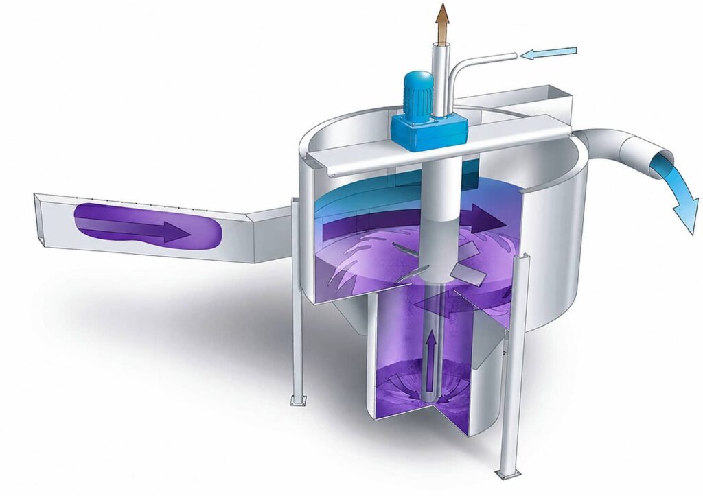
A forced-vortex grit chamber uses a rotating paddle or propeller — driven by a motor above the chamber — to maintain a controlled spiral flow within a cylindrical tank. Wastewater enters tangentially and exits over a central weir. The rotating flow creates centrifugal force on dense particles. Grit migrates outward and downward into a central collection hopper. Organic particles, being less dense, remain in the rotational flow and exit with the overflow.
The paddle speed is variable and adjusts automatically to maintain the target vortex velocity as inlet flow changes. This is the defining advantage of vortex technology: the separation mechanism is mechanically controlled and largely independent of hydraulic flow rate. Performance stays relatively consistent from minimum dry-weather flow to peak wet-weather flow.
How an Aerated Chamber Separates Grit
An aerated grit chamber is a rectangular channel with diffused air rising from one sidewall. The rising air creates a helical roll pattern — water rotates in a spiral as it travels down the channel length. Grit settles to the bottom trough under gravity while the rolling action keeps organic particles suspended. The settled grit is extracted by an air lift or screw conveyor.
The separation depends on maintaining a target horizontal velocity — typically 0.25–0.40 m/s — that resuspends organics while allowing grit to settle. This velocity is set by channel geometry and inlet flow rate. It is not mechanically controlled. As flow varies, horizontal velocity varies, and performance changes accordingly.
Hydraulic Performance Across the Flow Range
Flow variability is the most important factor in the vortex vs aerated grit chamber decision. Most municipal plants operate across a wide flow range — minimum dry-weather flows at night may be 20–30% of average, while peak wet-weather flows may reach 300–500% of average in combined sewer systems.
Vortex Chamber Performance Across Flow Ranges
Vortex chambers maintain good separation efficiency across a 5:1 or even 10:1 flow range. As inlet flow drops, the paddle speed adjusts downward to maintain the target vortex velocity. As flow rises to peak, paddle speed increases. The centrifugal separation mechanism remains active and calibrated throughout. Capture efficiency for 0.2 mm particles in a correctly sized and operated vortex chamber typically stays within 85–95% across the design flow range.
This flow-range performance is the primary reason vortex chambers dominate new installation specifications at plants with significant wet-weather variation. Combined sewer systems, plants serving older networks with high infiltration, and facilities in high-rainfall climates all benefit from flow-independent separation.
Aerated Chamber Performance Across Flow Ranges
Aerated chambers perform best within a relatively narrow band around the design flow. At flows significantly below design, horizontal velocity drops below the target range. Organic material begins to settle along with the grit, contaminating the collected fraction. The grit extracted becomes organic-rich, handling becomes more difficult, and disposal costs rise.
At flows above design, horizontal velocity exceeds the target. Fine grit that would settle at design flow gets carried through with the overflow. The chambers capture the coarser fraction but miss the fine sand and mineral fines that cause the most downstream abrasion damage. This failure mode is invisible — the chamber looks like it is operating, grit is being extracted, but fine particle capture has fallen significantly.
Managing Aerated Chamber Flow Range
Managing an aerated chamber across a wide flow range requires multiple parallel channels. Taking channels offline at low flow and bringing them online at peak maintains the horizontal velocity in each operating channel within acceptable bounds. This adds civil cost and operational complexity — but it works. Plants that specify a single aerated channel for a 4:1 flow range are accepting poor performance at the extremes, whether or not the design documents acknowledge it.
40,000 m³/day plant with a combined sewer system. Original headworks design specified two aerated grit chambers in parallel — sized for average flow in each channel. During design, the peak wet-weather flow calculation was based on a 1-in-5-year storm event. In practice, the actual peak-to-average ratio was closer to 4.5:1 due to significant infiltration from an aging network.
During wet season, both channels operated simultaneously at above-design horizontal velocity. Quarterly inspection of pump impellers downstream showed characteristic abrasive wear patterns within eighteen months of commissioning. A grit survey — measuring grit accumulation on the primary settler floor — found roughly 200 mm of grit accumulation after two years. The aerated chambers were capturing the coarse fraction but missing the fine sand. Retrofitting a vortex chamber on a third parallel channel, designed for peak overflow, resolved the fine grit problem at roughly $140,000 additional capital cost. The retrofit had not been in the original budget.
Energy Consumption: The 20-Year Cost Nobody Puts in the Budget
Energy is where the vortex vs aerated grit chamber comparison shifts most decisively in favour of vortex technology — and where the decision is most often made incorrectly by focusing only on capital cost.
Aerated Chamber Energy Use
An aerated grit chamber requires a continuous compressed air supply to the floor diffusers. The blower or compressor runs continuously during operation. Air flow rate is typically 0.15–0.45 m³ of air per m³ of wastewater processed. For a 50,000 m³/day plant, that translates to roughly 350–1,050 m³ of air per hour. A blower serving this duty consumes approximately 15–30 kW continuously.
Over twenty years of operation at a blended electricity rate of $0.10/kWh, that blower consumes $260,000–$525,000 in electricity — for grit removal alone. This figure does not appear in the capital cost comparison. Vendors of aerated chamber equipment have no incentive to present it. Design engineers using lowest-capital-cost selection criteria have no incentive to calculate it. The operations team inherits the energy bill.
Vortex Chamber Energy Use
A vortex chamber paddle drive is typically 1.5–5.5 kW, running intermittently at variable speed. At average duty, continuous equivalent power is often 1–3 kW. Over twenty years at the same electricity rate, the vortex paddle consumes $17,500–$52,500 in electricity — roughly one-tenth of the aerated chamber cost.
The energy penalty of aerated chambers is structural. It does not go away with better operations or newer equipment. Diffused air grit removal requires energy to create the roll pattern; there is no low-energy alternative within the aerated chamber operating principle. Vortex chambers use energy only to maintain the paddle rotation, which is mechanically efficient.
Grit Capture Efficiency: What the Numbers Actually Mean
Both chamber types claim 85–95% capture efficiency for 0.2 mm particles under design conditions. This number is frequently misread as a meaningful performance comparison. It is not, for two reasons.
Design Conditions vs Operating Conditions
The 85–95% figure applies at design flow, with correct air rates, correct paddle speed, and a correctly sized chamber. Aerated chambers operating above or below design flow see capture efficiency fall significantly. Vortex chambers maintain performance across a wider range, as discussed above. The design-condition efficiency figure does not reflect the time-averaged performance of either chamber type across the full operating flow range.
A more meaningful metric is capture efficiency weighted by the flow distribution — the time-averaged capture rate across all flow conditions, not just at design flow. This figure is almost never presented in vendor data sheets, because it requires a plant-specific flow frequency analysis. Calculating it for your specific plant, using measured or estimated flow duration curves, gives a more honest basis for comparison than catalogue specifications.
Fine Particle Capture
For particles below 0.15 mm, both chamber types show declining efficiency. However, vortex chambers maintain centrifugal separation for fine particles even as flow varies, while aerated chambers lose fine particle capture first when horizontal velocity rises above design. Fine particles — fine sand, mineral fines, glass — cause proportionally more abrasive damage per unit mass than coarse grit, because they reach tighter mechanical clearances. This makes fine particle capture the more important performance dimension for downstream equipment protection.
Maintenance Requirements: Honest Assessment
Maintenance requirements differ substantially between the two types. Any honest assessment goes beyond component count. Access difficulty, failure consequences, and operations capability all shape which technology is easier to maintain long-term.
Vortex Chamber Maintenance
The primary maintenance items on a vortex chamber are the paddle drive — motor, gearbox, shaft seal — and the grit extraction system. The shaft seal is the critical item. It operates at the interface between the submerged paddle shaft and the above-water drive housing. Seal failure allows wastewater ingress to the gearbox. Seal replacement requires taking the chamber offline and draining it — a planned 4–8 hour shutdown per chamber.
Annual seal inspection is the recommended interval. In practice, many operators extend this to 18–24 months if no seal weeping is detected. Seal replacement cost is low — the seal itself is a minor consumable. The downtime and labour are the real cost, which is why planned replacement is preferable to reactive replacement after failure.
The paddle and hub assembly should be inspected at 3–5 year intervals for wear and corrosion. Abrasive grit particles circulating in the vortex do cause wear on the paddle edges over time. Hardened paddle materials — available on most modern designs — extend wear life significantly. In high-grit environments, inspect paddles annually.
Aerated Chamber Maintenance
Aerated chambers have no submerged rotating components. The diffusers, air supply pipework, and grit extraction system are the maintenance items. Diffusers block over time with mineral deposits and biofilm. Blocked diffusers create uneven air distribution — the roll pattern becomes asymmetric, separation efficiency drops, and organic carryover into the grit increases. Diffuser cleaning or replacement is typically needed every 2–5 years depending on water quality.
The blower or compressor is a significant maintenance item that vortex chambers do not have. Blower maintenance — filter replacement, belt inspection, bearing lubrication — is a routine scheduled task. Blower failure stops the aerated chamber entirely. A standby blower is good practice at plants above 10,000 m³/day where grit chamber bypass would be a regulatory issue. Standby blower capital cost adds to the total comparison.
The grit extraction screw or air lift system is common to both chamber types and requires similar maintenance on both. This component does not differentiate the technologies in the maintenance comparison.
The aerated chamber “has no submerged moving parts” argument is technically true but operationally incomplete. What it has instead is a continuous-duty blower — a mechanical system with its own maintenance demands, failure modes, and standby requirements. Trading a paddle seal for a blower is not obviously simpler. At plants with limited mechanical maintenance capability, a failed paddle seal is a contained problem. A failed blower takes the grit chamber offline entirely until a replacement part arrives. Know which failure mode your operations team handles better before making the maintenance argument either way.
Capital Cost Comparison
Aerated chambers generally cost less per unit capacity than vortex chambers at the equipment procurement level. The differential varies by size and manufacturer but is typically 15–30% lower capital cost for aerated equipment.
Where the Capital Cost Comparison Breaks Down
The equipment procurement comparison misses several civil and ancillary cost items that narrow or reverse the advantage. Aerated chambers require a larger footprint — typically 30–50% more plan area for equivalent duty. In constrained headworks sites, this means larger civil structures. The blower system — blower, piping, controls, standby unit — adds capital cost that the vortex paddle drive does not generate. Multiple parallel aerated channels may be needed to manage the flow range, where a single vortex chamber might suffice.
Additionally, vortex chambers can sometimes be installed as in-channel retrofits in existing headworks, reusing existing civil structures with modifications. Aerated chambers require purpose-built rectangular channels with specific geometry. Retrofit flexibility adds capital value to vortex technology that does not appear in new-installation comparisons.
| Factor | Vortex Chamber | Aerated Chamber |
|---|---|---|
| Equipment capital cost | Higher (15–30% premium) | Lower |
| Civil footprint | Smaller | Larger (30–50% more area) |
| Ancillary systems | Paddle drive only | Blower + standby + piping |
| Channels needed for flow range | Fewer (variable speed paddle) | More (fixed geometry) |
| Annual energy cost (50,000 m³/d) | ~$2,000–5,000 | ~$13,000–26,000 |
| 20-year energy cost | ~$40,000–100,000 | ~$260,000–520,000 |
| Key maintenance item | Paddle shaft seal (annual inspection) | Blower + diffusers (ongoing) |
| Flow range performance | Good (variable speed) | Fair (fixed geometry) |
| Retrofit suitability | Good | Limited |
| Preferred application | Combined sewers, wide flow range, energy-sensitive | Separate sewers, stable flow, simple operations |
When to Choose a Vortex Grit Chamber
Vortex chambers earn their premium in specific conditions. Choose vortex technology when the plant serves a combined sewer system with significant wet-weather variation — the flow-range performance advantage is substantial and directly reduces downstream equipment wear. Also choose vortex when the headworks site is constrained and footprint is limited. Furthermore, choose vortex when lifecycle energy cost is a design criterion — and it should be on any project with a 20-year horizon.
Retrofit projects strongly favour vortex technology. The compact cylindrical geometry fits into existing headworks structures with less civil modification than a new aerated channel requires. Several manufacturers offer modular vortex units designed specifically for in-channel installation, which further reduces civil cost.
When to Choose an Aerated Grit Chamber
Aerated chambers are appropriate when the plant serves a separate sewer system with a relatively stable flow range — the fixed-geometry hydraulic performance is adequate when the flow range is 2:1 or less. They also suit large new plants where multiple parallel channels are planned regardless of grit chamber type, because multiple channels manage the flow range issue that aerated chambers face.
Aerated Chambers: The Operations Simplicity Argument
Operations simplicity is a genuine argument for aerated chambers at plants where mechanical maintenance capability is limited. No submerged rotating shaft to seal. No variable-speed drive to calibrate. The blower is a familiar piece of equipment to most operations teams — more familiar, in many cases, than a vortex paddle drive and controller. In remote locations where specialist mechanical contractors are not readily available, the aerated chamber’s simpler mechanical profile can be the right operational choice even at a higher energy cost.
15,000 m³/day plant serving a mixed light-industrial catchment with significant food processing discharge. Flow range was approximately 3:1 peak to minimum. The design team initially specified aerated grit chambers based on lower capital cost and familiarity. A lifecycle cost analysis was requested by the client after they reviewed an earlier project where aerated chamber energy costs had exceeded the capital saving within four years.
A 20-year energy cost difference of roughly $180,000 favoured vortex technology, against a capital cost premium of $45,000 for the vortex units. One fewer parallel channel was also required due to flow-range performance, saving an additional $60,000 in civil cost. The project switched to vortex chambers. At commissioning, the operations manager noted that the variable-speed controller took two weeks to dial in — and nobody touched it again after that.
Specifying Either Chamber Type: What to Lock Down
Regardless of which type is selected, several specification parameters are routinely left to vendor defaults — and defaults are calibrated for average conditions, not for your plant.
For Vortex Chambers
State the paddle speed range and the control logic for automatic speed adjustment with flow. Confirm the design particle — 0.2 mm at SG 2.65 is standard, but verify it matches your catchment. Specify shaft seal type and inspection access arrangement. Request capture efficiency data at minimum, design, and peak flow — not just at design flow. Confirm extraction system type and extraction cycle frequency recommendation.
For Aerated Chambers
State the target horizontal velocity at design flow, minimum flow, and peak flow. Define the air flow rate range and the control approach for varying air rate with flow. Specify diffuser type and cleaning interval. Confirm whether a standby blower is included in scope. Request capture efficiency data across your plant’s actual flow range — not just at the nominal design flow from the catalogue. Lock channel dimensions into the specification; do not leave geometry to vendor recommendation without independent hydraulic verification.
FAQ
Vortex vs Aerated Grit Chamber FAQ: Selection
Vortex vs Aerated FAQ: Sizing and Performance
Choosing Between Vortex and Aerated Grit Removal?
Morvolous Engineering Team builds the lifecycle cost analysis, sizes each option for your actual flow range, and presents the comparison without vendor bias. Reach out before the headworks design is locked in.
Contact Morvolous →