
How DAF systems work, where they outperform sedimentation, and the operating variables that determine whether you get clean effluent or a floated sludge problem
Dissolved air flotation is one of those processes that looks straightforward in a textbook and reveals its complexity in operation. The principle is simple: dissolve air into water under pressure, release that pressure, and microbubbles attach to suspended particles and float them to the surface for removal. The DAF system then skims the float layer off the top. In practice, bubble size distribution, recycle ratio, chemical conditioning, hydraulic loading, and float blanket management all interact. The difference between 95% and 60% suspended solids removal often comes down to one of these variables being off. This guide covers the full DAF system — how it works, where it fits in treatment processes, how to size it, and the operational variables that matter most.
The focus here is on pressurised recycle DAF — the dominant configuration in municipal and industrial wastewater treatment. Induced air flotation (IAF) and electrolytic flotation are noted where relevant but follow different operating principles.
For context on DAF as part of broader wastewater treatment process design, the Water Environment Federation addresses flotation thickening and clarification in its Manual of Practice series, including design criteria and performance benchmarks that inform the discussion below.
How a DAF System Works: The Physics
Understanding DAF performance starts with the physics of bubble generation and particle attachment. These are not academic details — they directly determine what goes wrong when a DAF system underperforms.
Bubble Generation: Pressure Dissolution and Release
In a pressurised recycle DAF, a portion of the treated effluent — typically 15–50% of the inlet flow — is recycled and pumped to a pressurisation tank at 400–600 kPa gauge pressure. Air saturates into the recycle stream at this pressure. Henry’s Law governs the dissolution: air solubility increases with pressure. The saturated recycle stream then releases through a pressure-reducing valve into the flotation tank at atmospheric pressure.
The sudden pressure drop causes dissolved air to come out of solution as microbubbles. Bubble diameter depends on the degree of supersaturation and the nucleation conditions at the release valve. Well-designed systems produce bubbles in the 10–100 micron range. Larger bubbles — from turbulent release or poor valve design — reduce contact efficiency with small particles. Bubble size is one of the parameters vendors rarely disclose explicitly; it is worth asking for.
Particle-Bubble Attachment
Microbubbles attach to suspended particles through three mechanisms: collision and adhesion, entrapment within floc structures during chemical conditioning, and nucleation directly on particle surfaces. Collision and adhesion dominate in well-conditioned systems. The rate of particle-bubble contact depends on bubble concentration, particle concentration, and the relative velocity between them.
This is why chemical conditioning — coagulation and flocculation upstream of the DAF — is so critical. Well-formed floc presents more surface area and more nucleation sites for bubble attachment. Poorly conditioned feed produces small, dense primary particles that bubbles contact but cannot lift. A DAF system with poor chemical conditioning consistently underperforms, regardless of how well the hydraulic design was executed.
Float Layer Formation and Removal
As particle-bubble aggregates rise to the surface, they form a float blanket — a layer of concentrated sludge at the water surface. Float blanket depth and consistency determine skimmer performance. A thin, uniform float layer skims cleanly. A deep, uneven layer — caused by overloading, poor chemical conditioning, or excessive hydraulic disturbance — leaves unskinned zones and re-entrains float into the subnatant.
Skimmer design varies between manufacturers. Chain-and-flight skimmers, rotating drum skimmers, and oscillating blade skimmers each handle different float consistencies. The right choice depends on float solids concentration — which depends on chemical dosing and hydraulic loading — not just on vendor preference.
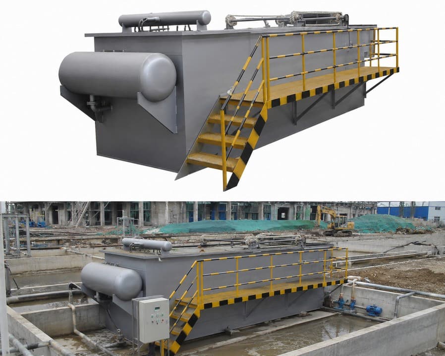
DAF System Components: What Each Part Does
A complete DAF system consists of several integrated components. Each has a specific function and specific failure modes.
Pressurisation System
The pressurisation system comprises the recycle pump, pressurisation tank (or saturator), air injection point, and pressure control valve. The recycle pump must maintain stable flow against the saturation pressure — typically 400–600 kPa. Pump cavitation from air entrainment is a common problem when the pump suction draws from a turbulent point in the system. Locate the recycle pump suction at a calm point in the treated effluent zone, not near the inlet or skimmer discharge.
The saturator — a packed vessel or simple pipe arrangement — provides contact time between the pressurised recycle and injected air. Packed saturators achieve higher air dissolution efficiency but require periodic cleaning of the packing material. Pipe saturators are simpler and need less maintenance, but achieve lower saturation efficiency at the same pressure. For most applications, pipe saturators with 400–600 kPa operating pressure are adequate. Packed saturators earn their cost premium only at very high recycle ratios or where air consumption is a meaningful operating cost.
Flotation Tank
The flotation tank is the main separation vessel. It receives the combined flow of incoming feed and saturated recycle. The feed enters through a contact zone — typically a baffled section at the inlet — where bubble release occurs and particle-bubble attachment takes place. Flow then passes through the separation zone, where float rises and clarified subnatant flows under a baffle to the effluent outlet.
Flotation tank hydraulics determine how uniformly flow distributes across the tank width. Non-uniform flow creates fast-moving channels where residence time is too short for effective flotation, alongside stagnant zones where settled sludge accumulates. Inlet baffle design and the distribution of the recycle release points across the tank width are the primary variables. Both are engineering decisions made at design stage — they cannot be adjusted in operation.
Recycle Release Valves
Pressure release valves control the transition from pressurised recycle to atmospheric pressure in the flotation tank. Valve design directly affects bubble size distribution. A valve that releases too rapidly creates large bubbles from turbulent nucleation. One that releases too slowly limits throughput. Most modern DAF systems use needle valves or proprietary release nozzles that produce consistent bubble release across a range of flow conditions.
Release valve fouling is a maintenance item that receives insufficient attention. Mineral deposits and biofilm on the valve seat change the release geometry and alter the bubble size distribution — reducing contact efficiency. In hard water areas or systems with high calcium content, valve cleaning at 3–6 month intervals maintains performance. In soft water or treated effluent recycle systems, annual cleaning is typically adequate.
Skimmer and Float Handling
The skimmer removes the float blanket from the water surface and transfers it to the float sludge collection trough. Skimmer speed — the rate at which the skimmer blade or flight traverses the tank — must match the rate of float accumulation. Too slow, and the float blanket deepens until it becomes unstable and re-entrains into the subnatant. Too fast, and the skimmer introduces hydraulic disturbance that breaks up the float layer before collection.
Float sludge concentration — the solids content of the material leaving the skimmer — is a key operational parameter. Higher float solids reduce the volume of sludge for downstream thickening or dewatering. Chemical conditioning has the largest influence on float solids concentration. Adequate polymer dosing produces a firm, coherent float that skims at 3–6% dry solids. Insufficient polymer produces a thin, watery float at 0.5–1.5% dry solids — much larger volume for the same mass of solids.
| Component | Function | Key Failure Mode | Maintenance Item |
|---|---|---|---|
| Recycle pump | Pressurise recycle stream | Cavitation from air entrainment | Impeller inspection, seal replacement |
| Saturator | Dissolve air into recycle | Packing fouling (packed type) | Periodic cleaning |
| Release valves | Generate microbubbles | Fouling changes bubble size | Cleaning at 3–12 month intervals |
| Flotation tank | Separate float from subnatant | Non-uniform flow distribution | Baffle inspection, desludging |
| Skimmer | Remove float blanket | Speed mismatch with float rate | Drive chain, blade wear |
| Chemical dosing | Condition feed for flotation | Under/over-dosing | Jar testing, dose optimisation |
Where DAF Fits in the Treatment Process
DAF is not a universal clarification technology. It outperforms sedimentation in specific conditions and underperforms in others. Choosing correctly requires understanding the feed characteristics, not just the removal targets.
DAF vs Sedimentation: The Density Argument
Sedimentation separates particles by letting them sink under gravity. It works well for dense, discrete particles — mineral sediments, heavy inorganic floc. DAF separates particles by floating them. It works well for low-density particles — fats, oils, greases, biological floc, algae, and light organic material — that settle slowly or not at all.
This is the fundamental selection criterion. Feed streams with high fat, oil, and grease (FOG) content respond poorly to sedimentation. The FOG fraction floats rather than settling, creating a scum layer that disrupts the settler and passes into the effluent. The same feed stream responds well to DAF. A feed stream dominated by dense mineral particles — heavy clay, sand fines, metal hydroxide precipitates — separates more efficiently in a settling tank or lamella clarifier than in a DAF.
Primary Applications
Food processing wastewater is the most common industrial DAF application. Slaughterhouses, dairy plants, fish processing, beverage production, and edible oil refining all generate high-FOG wastewater that requires DAF for effective primary treatment. The DAF removes 70–95% of FOG and 60–85% of suspended solids, reducing the organic load on the downstream biological treatment stage.
Municipal wastewater applications include flotation thickening of waste activated sludge and primary sludge. DAF thickening achieves 4–8% dry solids in the thickened sludge — higher than gravity thickening for light biological sludge. It is also used as a tertiary polishing step after biological treatment, particularly for phosphorus removal through chemical precipitation and flotation.
Paper and pulp mills use DAF to recover fibre from process water — both for water reuse and fibre recovery. Textile and tannery effluent treatment uses DAF to remove dye particles and chemical precipitates that resist sedimentation. In each case, the common factor is low-density target particles that benefit from the upward lift mechanism of flotation rather than the downward gravity mechanism of sedimentation.
Where DAF Is Not the Right Choice
DAF is not appropriate for streams dominated by dense, discrete particles. It adds capital and operating cost without performance benefit over a correctly sized settling tank. Very high suspended solids feeds — above roughly 2,000–3,000 mg/L — are also poorly suited to DAF. Float blanket depth and sludge handling capacity become limiting factors at those concentrations. In these cases, a pre-treatment step to reduce solids loading before the DAF is required.
I have seen DAF systems specified for applications where sedimentation would have done the job at lower capital and operating cost — simply because DAF was the designer’s default for food industry wastewater. FOG content is the key variable. If the feed has high FOG, DAF is the right tool. If the FOG content is low and the dominant pollutant is settleable suspended solids, a lamella settler or sedimentation tank is often more economical. Do not specify DAF because the industry normally uses it. Specify it because the feed characteristics require it.
DAF System Sizing: The Key Parameters
DAF sizing starts with hydraulic loading rate — the most important single parameter — and builds from there through recycle ratio, air-to-solids ratio, and tank geometry.
Hydraulic Loading Rate
Hydraulic loading rate (HLR) is the total flow — inlet plus recycle — divided by the flotation tank surface area. Units are m³/m²/hour. Most municipal and industrial DAF systems design for 3–10 m³/m²/hour, with food industry applications typically at the lower end where FOG and solids concentrations are highest.
Exceeding the design HLR reduces residence time in the separation zone. Particle-bubble aggregates do not reach the surface before the subnatant exits the tank. Suspended solids removal efficiency falls. HLR exceedance during peak flow events is the most common operational cause of DAF underperformance. It is also the cause operators most often misattribute to chemical dosing.
Recycle Ratio
Recycle ratio is the recycle flow divided by the inlet flow, expressed as a percentage. Typical values are 15–50%. Higher recycle ratios produce more bubbles per unit of inlet flow, improving contact efficiency with particles. However, they also increase the hydraulic load on the flotation tank and the energy consumption of the recycle pump.
Recycle ratio selection depends on the feed suspended solids concentration. Higher suspended solids require higher recycle ratios to provide adequate bubble contact. A recycle ratio of 15–25% suits low-solids feeds — municipal secondary clarifier overflow, lightly contaminated process water. Feeds with 500–2,000 mg/L suspended solids typically require 30–50% recycle ratio for adequate performance.
Air-to-Solids Ratio
The air-to-solids ratio (A/S ratio) relates the mass of dissolved air released in the flotation tank to the mass of suspended solids in the inlet feed. It provides a measure of whether sufficient bubbles are available to float the incoming solids. The target A/S ratio for most applications is 0.005–0.060 mL air per mg of suspended solids.
Calculating A/S ratio requires knowing the dissolved air concentration in the recycle (a function of saturation pressure and temperature), the recycle flow rate, and the feed suspended solids concentration. A/S ratio below the target range indicates insufficient bubbles for the solids load — increase recycle ratio or saturation pressure. A/S ratio above the target range adds operating cost without proportional performance improvement.
Tank Geometry and Depth
Flotation tank depth for pressurised recycle DAF is typically 1.5–3.0 m. Shallower tanks are sometimes used in retrofit applications where headroom is limited. Deeper tanks provide more residence time in the contact zone and better tolerance of hydraulic variation. Width-to-length ratio for rectangular tanks is typically 1:3 to 1:5 — long, narrow tanks produce more uniform flow distribution than square tanks.
Circular DAF tanks — common in thickening applications — distribute flow radially from a central inlet. They handle variable flow better than rectangular tanks but are less efficient per unit area at high hydraulic loading rates. For primary separation applications, rectangular tanks are generally preferred above 100 m³/hour design flow.
Poultry processing plant, 1,800 m³/day. The DAF was originally sized for an HLR of 5.5 m³/m²/hour at average flow. During seasonal production peaks — when the plant ran three shifts instead of two — inlet flow increased to approximately 1.4× average. Combined with the fixed recycle flow, the effective HLR rose to nearly 8 m³/m²/hour during peak shifts.
Suspended solids in the DAF effluent during peak shifts averaged 280 mg/L — nearly triple the 95 mg/L achieved at average flow. The plant manager initially attributed the problem to polymer dosing and repeatedly adjusted coagulant and flocculant doses without improvement. A hydraulic audit — measuring actual inlet flow and recycle flow against the design parameters — identified the HLR exceedance within one morning. Increasing recycle pump capacity to maintain recycle ratio at peak flow brought effluent suspended solids back to below 110 mg/L during peak production periods. The recycle pump upgrade cost roughly $12,000 — less than four months of excess biological treatment costs from the elevated DAF effluent load.
Chemical Conditioning for DAF
Chemical conditioning — coagulation followed by flocculation — is the most influential operational variable in DAF performance. A DAF system with excellent hydraulic design and poor chemical conditioning will not achieve design removal efficiency. One with adequate hydraulic design and excellent chemical conditioning will often exceed design targets.
Coagulation
Coagulation destabilises the surface charge on suspended particles and colloidal material, allowing them to aggregate. Common coagulants for DAF applications include aluminium sulphate (alum), ferric chloride, ferric sulphate, and polyaluminium chloride (PAC). Each has different performance characteristics across pH ranges and temperature conditions.
Coagulant dose and pH are jointly optimised. Alum performs best at pH 6.5–7.5. Ferric coagulants have a wider effective pH range — 4.5–8.5 — making them more suitable for feeds with variable pH. PAC is more tolerant of temperature variation than conventional alum and produces less sludge volume per unit of turbidity removed. Select the coagulant based on feed pH, temperature range, and downstream sludge handling — not simply on unit cost.
Flocculation
Flocculation aggregates the destabilised primary particles into larger floc suitable for bubble attachment. Polymer flocculants — typically high molecular weight cationic or anionic polyacrylamide — are the standard for DAF applications. Polymer selection depends on the charge characteristics of the feed solids.
Mixing energy during flocculation is as important as polymer dose. Too much mixing energy breaks up forming floc. Too little fails to aggregate particles into bubble-attachable size. G-value — the root mean square velocity gradient — targets 10–50 s⁻¹ during flocculation for DAF, compared to 100–300 s⁻¹ during rapid mixing for coagulant dispersion. These energy levels require purpose-built mixing chambers or inline static mixers with correct geometry — not simply a injection point in the feed pipe.
Jar Testing for Dose Optimisation
Jar testing is the standard method for optimising coagulant and polymer dose at a specific set of feed conditions. A series of bench-scale tests at varying doses identifies the dose that produces the best floc formation and clarified supernatant. Jar testing should be performed at commissioning, after any significant change in feed characteristics, and seasonally if the feed composition varies with production cycles.
A common operational mistake is setting the coagulant dose at commissioning and not revisiting it as feed characteristics change. A food processing plant that shifts from beef to poultry processing, or introduces a new cleaning chemical, may see its optimal coagulant dose shift significantly. When DAF performance declines without any obvious equipment cause, run a jar test series before adjusting anything else.
DAF Float Sludge: Characteristics and Handling
Float sludge is the concentrated solids fraction removed from the DAF surface. Its characteristics — solids concentration, viscosity, organic content — determine downstream handling requirements and disposal cost.
Float Solids Concentration
Float solids concentration ranges from 0.5% dry solids for poorly conditioned, low-FOG feeds to 8–12% for well-conditioned, high-FOG food industry feeds. The target for most applications is 3–6% dry solids — concentrated enough to reduce downstream volume but fluid enough for pump handling without specialised equipment.
Achieving target float concentration requires correct polymer dosing, correct skimmer speed, and adequate float blanket depth. Skimming too frequently produces dilute float — the skimmer is removing surface water along with the float. Skimming too infrequently allows the float blanket to deepen and become unstable, eventually collapsing and re-entraining float into the subnatant.
Downstream Handling Options
DAF float sludge from food processing applications is typically high in organic content — 60–90% volatile solids. This makes it attractive for anaerobic digestion if the plant has digestion capacity. Alternatively, it can go directly to mechanical dewatering — belt press or screw press — before disposal. Screw press dewatering of DAF float from food processing plants typically achieves 18–25% dry solids output, which is suitable for composting or land application in most regulatory frameworks.
Municipal and Industrial Float Sludge Handling
Municipal DAF thickened sludge — from flotation thickening of waste activated sludge — is typically 4–8% dry solids and goes to anaerobic digestion or direct dewatering. The higher volatile solids content compared to gravity-thickened sludge makes DAF-thickened sludge a better digestion feedstock in terms of biogas yield per unit volume.
Milk powder and UHT milk production facility, 2,400 m³/day. The DAF had been operating for approximately eighteen months with consistently low float solids — averaging 1.2% dry solids against a design target of 4%. The float volume was approximately three times the expected design volume, overwhelming the downstream belt press capacity and requiring double the disposal runs.
Investigation found that the polymer injection point was located only 0.8 m upstream of the DAF inlet — completely inadequate contact time for floc formation before the feed entered the flotation zone. The floc was forming inside the flotation tank rather than in the flocculation zone, resulting in small, weak floc with poor bubble attachment. Relocating the polymer injection point to 8 m upstream and adding a gentle inline static mixer brought float solids up to 3.8% within two weeks. Disposal costs dropped by approximately 60%. The original injection point had been positioned based on pipe convenience, not process requirements. Nobody had reviewed it against the vendor’s flocculation residence time specification.
DAF Operational Monitoring and Control
Effective DAF operation requires monitoring several parameters simultaneously. An operator who monitors only one variable — typically effluent turbidity — will miss interactions between variables that explain most performance problems.
Key Operational Parameters
Monitor inlet flow rate — real time, not daily average. HLR exceedance during peak production periods is the most common undiagnosed performance problem. Monitor recycle flow rate and saturation pressure — together these determine bubble production rate. A recycle pump running at lower-than-design flow reduces bubble production and degrades performance without triggering any alarm. Monitor float blanket depth — too shallow indicates under-dosing or insufficient recycle; too deep indicates over-dosing or slow skimming. Monitor effluent turbidity or suspended solids — this is the output variable, not the control variable. Use it to diagnose problems, not to make dosing adjustments in isolation.
Operational Adjustments and Their Effects
Higher coagulant dose improves charge neutralisation but can over-coagulate — producing re-stabilised colloids that resist flocculation. More polymer improves floc size but can produce sticky floc that blinds the recycle release valves. A higher recycle ratio improves bubble contact efficiency but increases hydraulic load on the flotation tank. Faster skimmer speed removes float more quickly but can disturb the separation zone if taken too far.
Each adjustment has a primary effect and secondary consequences. Understanding the interaction prevents the common operational trap of making multiple simultaneous adjustments that mask the actual cause of underperformance.
FAQ
DAF System FAQ: Design and Selection
DAF System FAQ: Flow Range and Performance
DAF System FAQ: Operation and Troubleshooting
DAF System FAQ: Cleaning and Maintenance
Designing or Optimising a DAF System?
Morvolous Engineering Team works through feed characterisation, hydraulic sizing, chemical conditioning selection, and float handling design for dissolved air flotation systems. Reach out for a technical review before procurement or during operational troubleshooting.
Contact Morvolous →